ESP8266 is a device that nicely supports IoT functionality. But one of the downsides of the ESP8266 is the inadequate number of GPIOs or pins for input and output signals that can be used without a problem with the board’s functionality, so expanding ports for the ESP8266 is quite a thing that developers must be faced which can be performed in a several ways such as using PCF8574 as an expansion port via the I2C bus or connecting to Arduino via Serial Port to allow Arduino to work and send the results back via the serial communication port, etc. This article chose to use an Arduino Uno as a board for I / O to the ESP8266 by using the I2C bus operation.
The example in this experiment uses C / C ++ language for the Arduino Uno board and MicroPython for the ESP8266 board.
Experimental equipment
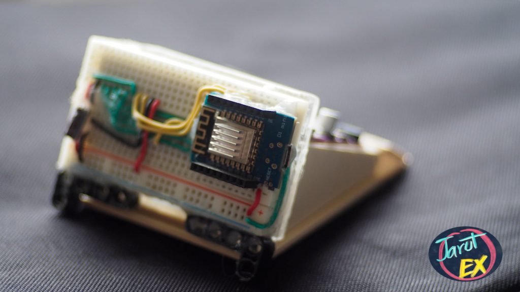
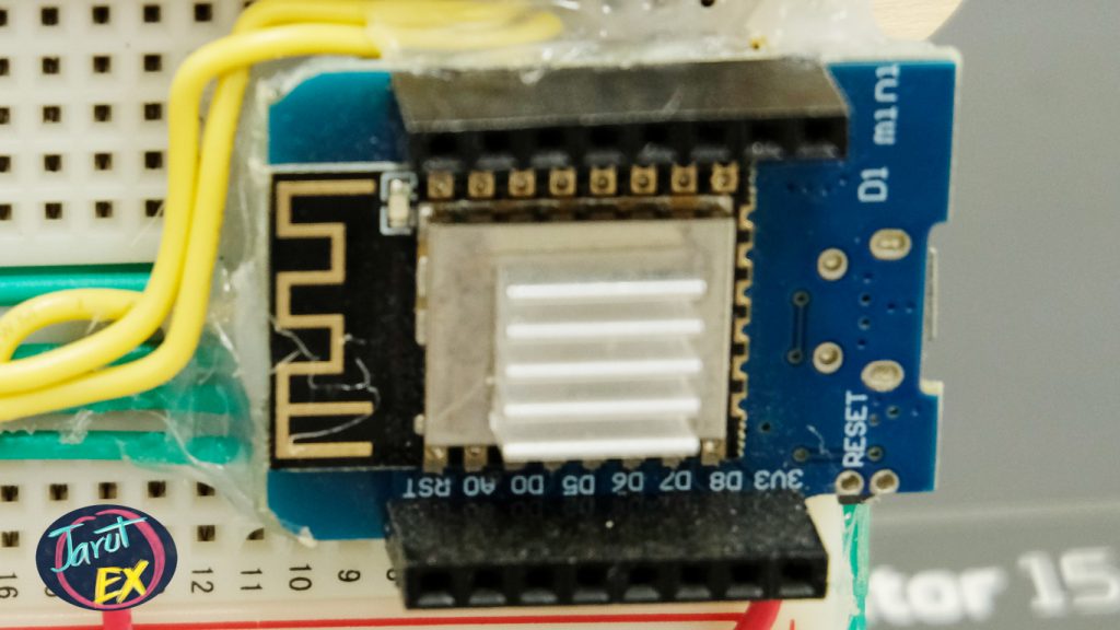
- ESP8266 (WeMos D1 mini)
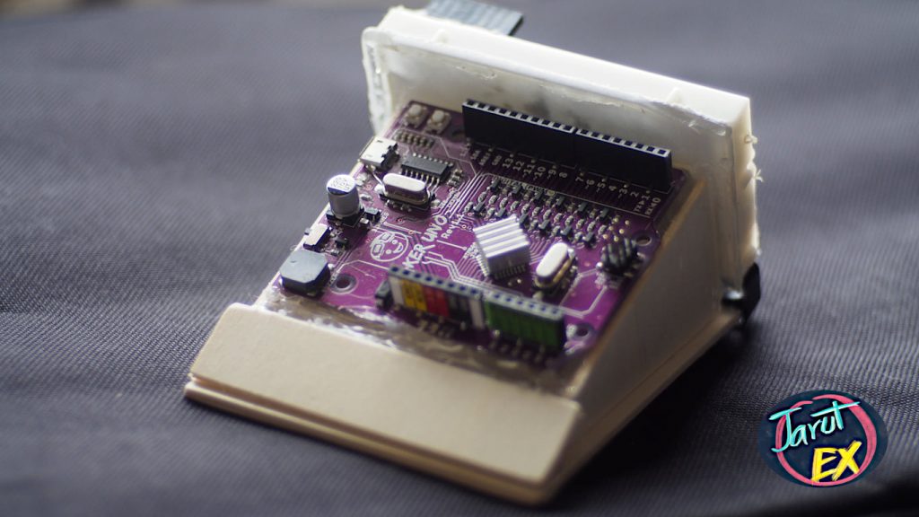
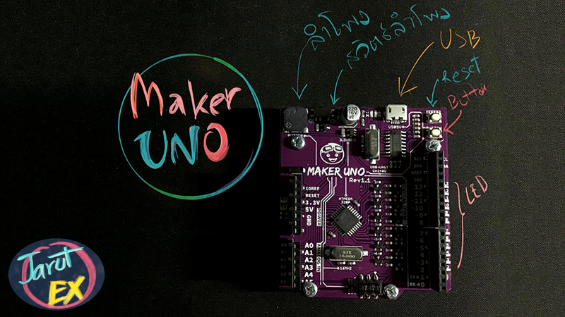
- Arduino Uno (Arduino Uno Maker)
- LED x 8 (Already on Arduino Uno Maker)
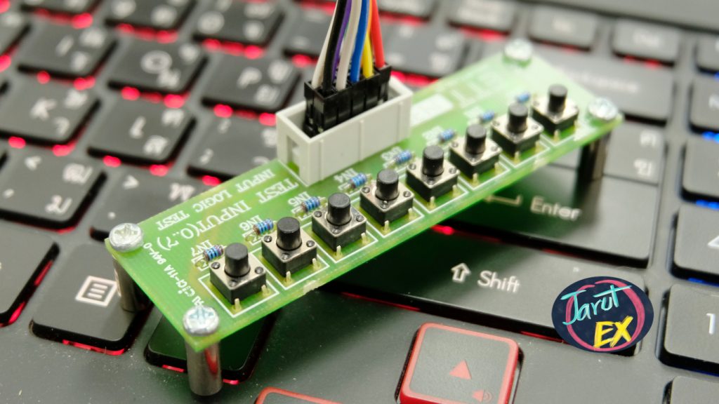
- SW x 8 (ET-TEST 10P/INP)
Pins connection
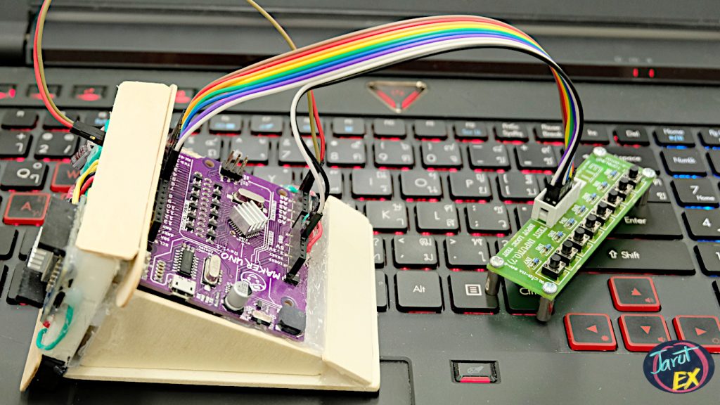
- Connection between ESP8266 and Arduino Uno Maker
D1 (GPIO5) –> [SDA] –> A4
D2 (GPIO4) –> [SCL] –> A5
- Connection between SWx8 and Arduino Uno Maker
D2 –> SW1
D3 –> SW2
D4 –> SW3
D5 –> SW4
D6 –> SW5
D7 –> SW6
D8 –> SW7
D9 –> SW8
5V –> VCC
GND –> GND
When the ET-TEST 10P / INP is working R-Pull up is applied cause the status of the input pin when the switch is not pressed to 1 and when the switch is pressed to 0.
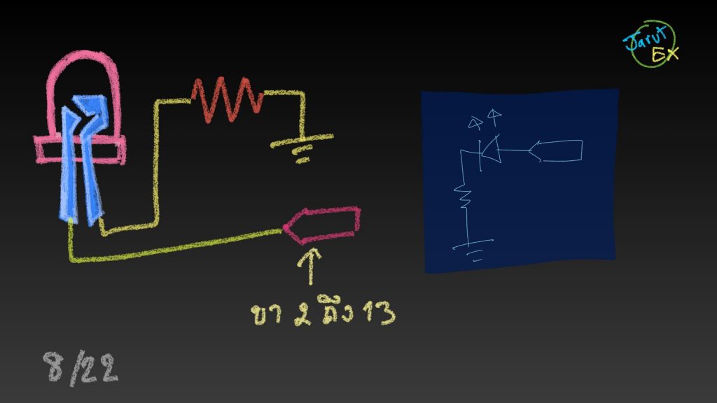
- The LED circuit of the Arduino Uno Maker board is shown in Figure 6, the lamp will turn on when the value 1 is sent to pins D2 through D13 and the lamp will turn off when 0 is sent to it.
Program for Arduino Uno
The operation of the Arduino Uno has 2 parts: the receiving from the I2C bus and the input to the I2C bus by configuring the address used to identify the devices connected to the I2C bus of the Arduino Uno to 7.
The format for receiving values from the bus used 2 bytes, the first one is byte 0 used for determines the command which is defined in 3 formats, as for byte 1 is used for commands supporting. The 3 commands are
0 for directing the LEDs connected to pins D2 to D9 to turn off (byte 1 is not used).
1 for directing LEDs connected to pins D2 to D9 (byte 1 is not used).
2 for directing LEDs connected to pins D2 through D9 to follow the pattern value read from byte 1.
As for function that responds to an I2C bus command is the i2cReceive () function that must be specified in the Wire.onReceive () function.
The programming code of the Arduino Uno is as code-01.
Reading data from the Arduino Uno is via the I2C bus, in this example it reads the switch states connected to ports D2 to D9 as shown in Figure 6. The function that responds when requesting data from the bus is i2cRequest () and The command to specify the response to a request for information is the command Wire.onRequest ()
// code-01 for Arduino Uno
#include <Wire.h>
int unoAddr = 7;
void i2cReceive( int bytes ) {
  uint8_t dInput = Wire.read();
  uint8_t pattern = Wire.read();
  Serial.println(dInput);
  if (dInput == 0) {
    for (int ledPin = 2; ledPin <= 9; ledPin++) {
      pinMode(ledPin, OUTPUT);
    }
    for (int ledPin = 2; ledPin <= 9; ledPin++) {
      digitalWrite(ledPin, 0);
    }
  }
  else if (dInput == 1) {
    for (int ledPin = 2; ledPin <= 9; ledPin++) {
      pinMode(ledPin, OUTPUT);
    }
    for (int ledPin = 2; ledPin <= 9; ledPin++) {
      digitalWrite(ledPin, 1);
    }
  }
  else if (dInput == 2) {
    for (int ledPin = 2; ledPin <= 9; ledPin++) {
      pinMode(ledPin, OUTPUT);
    }
    uint8_t mask = 0x01;
    for (int ledPin = 2; ledPin <= 9; ledPin++) {
      digitalWrite(ledPin, pattern & mask);
      mask <<= 1;
    }
  } else {
    return;
  }
}
void i2cRequest() {
  for (int ledPin = 2; ledPin <= 9; ledPin++) {
    pinMode(ledPin, INPUT_PULLUP);
  }
  uint8_t bitNo = 0;
  uint8_t unoBuffer = 0;
  for (int swPin = 2; swPin <= 9; swPin++) {
    unoBuffer |= digitalRead( swPin ) << bitNo;
    bitNo++;
  }
  Serial.println(unoBuffer, HEX);
  Wire.write(unoBuffer);
}
void setup() {
  Serial.begin(115200);
  Serial.println("UNO Started");
  Wire.begin(unoAddr);
  Wire.onReceive(i2cReceive);
  Wire.onRequest(i2cRequest);
}
void loop() {
}
Program of ESP8266
The ESP8266 code is connected to the I2C bus via SDA and SCL pins, the communication clock frequency is 10000, and the unoBuffer variable is created in a 2-byte array to be used for command instructions and send data to the Arduino Uno. The sample code according to code-02 commanded the Arduino UNO’s LEDs to turn off and on for 1 second each repeatedly. And the last is to read data from the Arduino Uno and display it on the terminal.
Command for creating I2C variables.
I2CVar = machine.I2C(sda=SDApin, scl=SCLpin, freq=Communicationfrequency )Command to create a variable for referencing the pin or port of the ESP8266.
pinVar = machine.Pin(pin)The command for sending data to the I2C bus has the following usage patterns:
I2CVar.writeto( deviceAddr, data )คำสั่งสำหรับอ่านข้อมูลจากบัส I2C จำนวน n ไบต์มีรูปแบบการใช้งานดังนี้
variable = I2CVar.readfrom( deviceAddr, numberOfBytesread )#code-02 for ESP8266
from machine import Pin, I2C
import time
sclPin = Pin(5)
sdaPin = Pin(4)
unoAddr = 7
unoBuffer = bytearray(2)
i2c = I2C(sda = sdaPin, scl = sclPin, freq=100000)
unoBuffer[0] = 0
unoBuffer[1] = 0
i2c.writeto(unoAddr, unoBuffer)
time.sleep_ms(1000)
unoBuffer[0] = 1
unoBuffer[1] = 0
i2c.writeto(unoAddr, unoBuffer)
time.sleep_ms(1000)
unoBuffer[0] = 2
unoBuffer[1] = 0xAA;
i2c.writeto(unoAddr, unoBuffer)
time.sleep_ms(1000)
dInput = i2c.readfrom(unoAddr,1)
print(dInput)Conclusion
From this article, you will find that Communication between devices via the I2C bus is not complicated. The principle of the device side is to set the device number, create a function to respond to requests for information and create a response function when receiving command/data. The controller side is responsible for writing and reading data you indicating the device’s address along with commands or importing data variables from the I2C bus. JarutEx team expects when readers experiment according to this article will build skills and understanding in programming to communicate between devices via the I2C bus. Have fun programming and creating new things.
If you want to discuss something, feel free to leave comments below.
(C) 2020, Danai Jedsadathitikul, Jarut Busarathid
Updated 2020/09/26