The ESP8266 is a device with a built-in WiFi connection system that can operate in both AP (Access Point) mode and client mode connected to an existing WiFi network or STA. The developer can set the name of the device (ESSID) or use the name according to the value set by the system to MicroPython-xxxx, where x represents the MAC Address of the device, the password is micropythoN (the developer can define a new one) with the IP address (IP Address) of 192.168.4.1.
Network basics
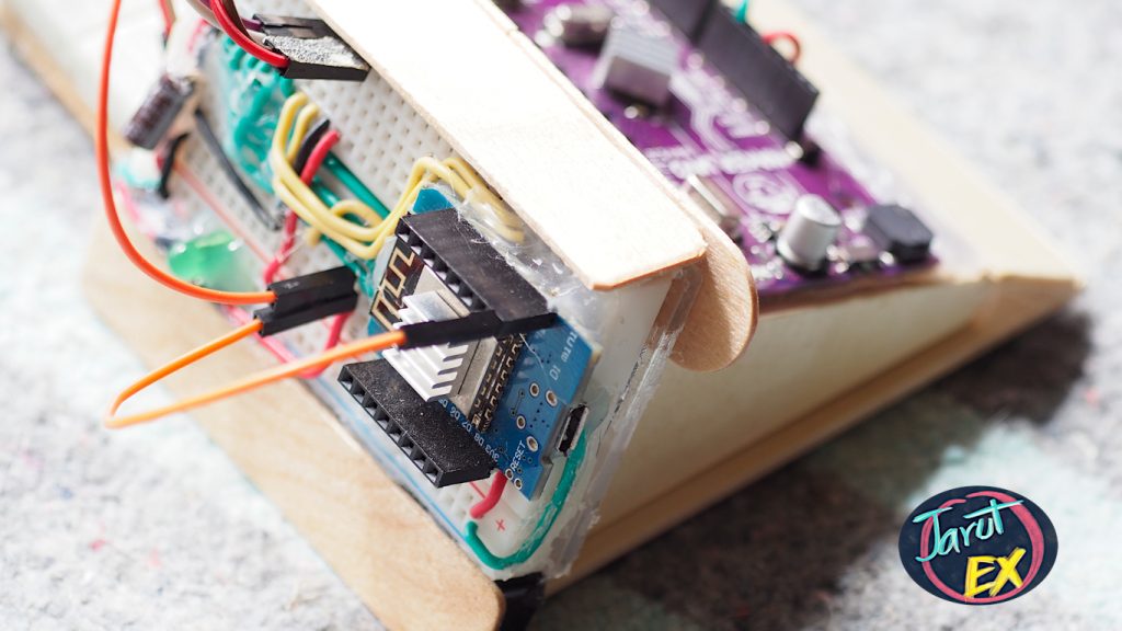
In this article, build on the previous article which communicating and controlling the Arduino Uno Maker via I2C bus communication. Thus this article will be commanding and seeing the status of these ports D2, D3, D4, D5, D6, D7, D8 and D9 of the Arduino Uno Maker via the ESP8266 web page.
#code3-1
import network as nw
ifSTA = nw.WLAN(nw.STA_IF)
print(ifSTA.active())
#code3-2
import network as nw
ifAP = nw.WLAN(nw.AP_IF)
print(ifAP.active())To read the settings of an interface, you can use the following commands to read the IP address, subnet mask, Gateway, and DNS.
#code3-3
import network as nw
ifAP = nw.WLAN(nw.AP_IF)
if (ifAP.active() == True):
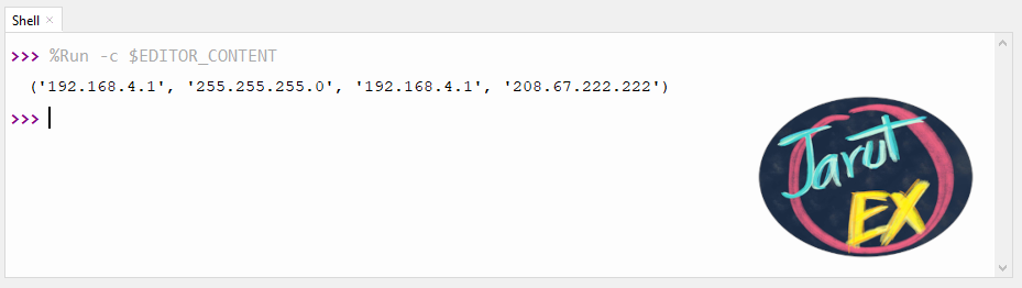
print(ifAP.ifconfig())ตัวอย่างภาพผลลัพธ์จาก code3-3 เป็นดังนี้
AP Mode
AP mode is used to sets the ESP8266 as a web service device. Users can connect to WiFi into this device to read information from the website, whose IP Address is 192.168.4.1 while the name of the ESSID and the password can be set by the developer.
The programming procedure in AP mode is as follows.
- Create an AP Interface
- Check Interface status if the status is False, use active() function and assign ESP8266 ESSID name and password.
- Create a function to send HTML data when the client connects.
- Read the setting value and display the result. (The AP can be skipped if you do not want to show the IP Address of the device, )
- Open the socket with port number 80 and wait for connection.
- Loop to wait for connection. When a connection occurs (the line after accept() will start), the developer can read the number of the connected device and the values obtained from the connection then the information is sent back to the browser of the connected device. After that, the connection must be closed.
Example code3-4 is an example of how to show “Hi JarutEx” text with page visit count
#code3-4
import socket
import network
import esp
#---(1)
ap = network.WLAN(network.AP_IF)
#---(2)
ssid = 'JarutEx-AP'
password = '123456789'
ap.active(True)
ap.config(essid=ssid, password=password)
counter = 0
while ap.active() == False:
  pass
print('Connection successful')
#---(3)
def web_page():
    global counter
    counter = counter + 1
    html = """<html><head><meta name="viewport"
      content="width=device-width, initial-scale=1"></head>
      <body><h1>Hi JarutEx. No."""
    html += str(counter)
    html += "</h1></body></html>"
    return html
#---(4)
print(ap.ifconfig())
#---(5)
s = socket.socket(socket.AF_INET, socket.SOCK_STREAM)
s.bind(('', 80))
s.listen(5)
#---(6)
while True:
    conn, addr = s.accept()
    print('conn {} from {}'.format(conn, addr))
    request = conn.recv(1024)
    print('request = {}'.format(request))
    response = web_page()
    conn.send('HTTP/1.1 200 OK\n')
    conn.send('Content-Type: text/html\n')
    conn.send('Connection: close\n\n')
    conn.send(response)
    conn.close()
STA Mode
In the case of connecting an ESP8266 to an existing WiFi network, the steps are as follows.
- Create an Interface variable that works in STA_IF mode.
- Check the availability status of the interface.
- Start the interface
- Create a connection to the WiFi network, if not connected successfully, loop the connection until successful.
- Read the settings that the network WiFi assigned to the ESP8266 board.
- Do the job required.
- Turn off function when not using.
Example code3-5 It is an example of how to connect to the network.
#code3-5
import network as nw
myESSID = "AP Name"
myPassword = "Password"
ifSTA = nw.WLAN(nw.STA_IF)
if (ifSTA.active() == False):
ifSTA.active(True)
ifSTA.connect(myESSID, myPassword)
while not ifSTA.isconnected():
pass
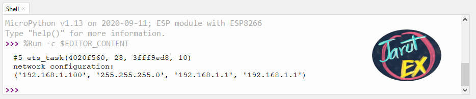
print("network configuration:\n{}".format(ifSTA.ifconfig()))
ifSTA.active(False)
Note
- 7th step is very important. If the developed program stops running without closing the interface, the ESP8266 will still attempt to connect to the WiFi network, a reset is required to restart the system.
- A network connection that requires authentication from the webpage before use will not work with this example. Readers need to use network sharing from their mobile phone to try out the program.
The example program shows a list of all access points that the ESP8266 board sees is as code3-6.
#code3-6
import network as nw
ifSTA = nw.WLAN(nw.STA_IF)
if (ifSTA.active() == False):
    ifSTA.active(True)
    listAPs = ifSTA.scan()
    for AP in listAPs:
        print("{}".format(AP[0]))
ifSTA.active(False)
Example of operating Arduino Uno via the web page.
An example code to command Arduino Uno Maker to turn on / off an LED and display the status of the LED connected to the ports D2, D3, D4, D5, D6, D7, D8 and D9 via the web page in AP mode can be written as code3-7 and code for Arduino Uno Maker is based on code3-8.
#code3-4
import esp
import time
import socket
import network
from machine import Pin, I2C

sclPin = Pin(5)
sdaPin = Pin(4)
unoAddr = 7
unoBuffer = bytearray(2)
unoStatus = 0
i2c = I2C(sda = sdaPin, scl = sclPin, freq=100000)

ap = network.WLAN(network.AP_IF)
ssid = 'JarutEx-AP'
password = '123456789'
ap.active(True)
ap.config(essid=ssid, password=password)
while ap.active() == False:
  pass
print('Connection successful')

def doOn():
    global unoBuffer
    global unoAddr
    unoBuffer[0] = 1
    unoBuffer[1] = 0
    i2c.writeto(unoAddr, unoBuffer)

def doOff():
    global unoBuffer
    global unoAddr
    unoBuffer[0] = 0
    unoBuffer[1] = 0
    i2c.writeto(unoAddr, unoBuffer)

def doReadStatus():
    global unoStatus
    global unoAddr
    unoStatus = i2c.readfrom(unoAddr,1)

def web_page():
    doReadStatus()
    html = """<html><head><meta name="viewport"
      content="width=device-width, initial-scale=1"></head>
      <body><h1>Status = """
    html += str(unoStatus)
    html += "</h1>"
    html += """<p><a href="/?led=on"><button>ON</button></a></p>
  <p><a href="/?led=off"><button>OFF</button></a></p>"""
    html += "</body></html>"
    return html

print(ap.ifconfig())
s = socket.socket(socket.AF_INET, socket.SOCK_STREAM)
s.bind(('', 80))
s.listen(5)
while True:
    conn, addr = s.accept()
    print('conn {} from {}'.format(conn, addr))
    request = str(conn.recv(1024))
    print('request = {}'.format(request))
    ledOn = request.find("/?led=on")
    ledOff = request.find("/?led=off")
    if (ledOn==6):
        doOn()
    if (ledOff==6):
        doOff()
    response = web_page()
    conn.send('HTTP/1.1 200 OK\n')
    conn.send('Content-Type: text/html\n')
    conn.send('Connection: close\n\n')
    conn.send(response)
    conn.close()
// code3-8 code for Arduino Uno
#include <Wire.h>
int unoAddr = 7;
uint8_t ledStatus[8] = {1, 1, 1, 1, 1, 1, 1, 1};
void i2cReceive( int bytes ) {
  uint8_t dInput = Wire.read();
  uint8_t pattern = Wire.read();
  Serial.println(dInput);
  if (dInput == 0) {
    for (int ledPin = 2; ledPin <= 9; ledPin++) {
      digitalWrite(ledPin, 0);
      ledStatus[ledPin-2] = 0;
    }
  }
  else if (dInput == 1) {
    for (int ledPin = 2; ledPin <= 9; ledPin++) {
      digitalWrite(ledPin, 1);
      ledStatus[ledPin-1] = 1;
    }
  } else {
    return;
  }
}
void i2cRequest() {
  for (int ledPin = 2; ledPin <= 9; ledPin++) {
    pinMode(ledPin, INPUT_PULLUP);
  }
  uint8_t bitNo = 0;
  uint8_t unoBuffer = 0;
  for (int ledIdx = 0; ledIdx < 8; ledIdx++) {
    unoBuffer |= ledStatus[ledIdx] << bitNo;
    bitNo++;
  }
  Serial.println(unoBuffer, HEX);
  Wire.write(unoBuffer);
}
void setup() {
  Serial.begin(115200);
  Serial.println("UNO Started");
  for (int ledPin = 2; ledPin <= 9; ledPin++) {
    pinMode(ledPin, OUTPUT);
    digitalWrite(ledPin, ledStatus[ledPin - 2]);
  }
  Wire.begin(unoAddr);
  Wire.onReceive(i2cReceive);
  Wire.onRequest(i2cRequest);
}
void loop() {
}
Conclusion
From this article, readers will be able to learn how to program the ESP8266 WiFi module in AP and STA mode by listing access points and programming to command the Arduino Uno Maker via the web page. Finally, the JarutEx team hopes that this article would be a guideline for studying device control programming with Python and useful for everyone in further application
If you want to discuss something, feel free to leave comments below.
Reference
https://docs.micropython.org/en/latest/esp8266/tutorial/network_basics.html
(C) 2020, Danai Jedsadathitikul/Jarut Busarathid
updated 2020-10-01