This article writes a library to operate character LCD modules using I2C bus operation, which uses a PCF8574 module designed to connect to the LCD. This makes it possible to use 2 command pins from ESP8266 to command the LCD module’s 8 pins, namely RS, R/W, EN, A, D0, D1, D2 and D3 simultaneously enable/disable the module backlight of LCD and the LCD module character sharpness can be adjusted from the variable resistor located on the PCF8574 module.
Equipment
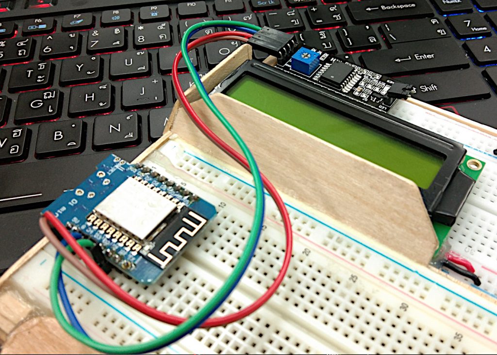
The equipment for this experiment was as follows:
- ESP8266
- A 16-column, 2-row or other size LCD module but the goto () method of the kjlcd library must be customized.
- 1602 2004 LCD Adapter Plate IIC I2C Interface, we hereby call it PCF8574 module for connection between the LCD module and ESP8266.
LCD-I2C
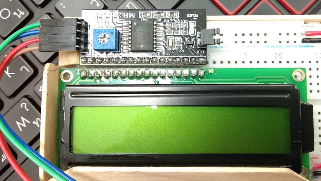
The PCF8574 module is a 4-bit parallel character LCD driver circuit that communicates with the ESP8266 through the I2C bus using the PCF8574 to be an 8-bit data transceiver from the I2C bus and sends the input to the LCD module. As a result, it can use only 2 pins of ESP8266 to controls a 4-bit module LCD (D0, D1, D2, D3) with RS, R / W, EN and A (LCD’s backlight on / off).
From figure 2, we founded that the use of the PCF8574 module is to be a connector with the LCD module which is a parallel connection and the PCF8574 module has a jumper to enable/disable the LCD backlight.
In addition, the PCF8574 module has a variable resistor for adjusting contrast or brightness. (Contrast / sharpness) of the characters that appear on the LCD module.
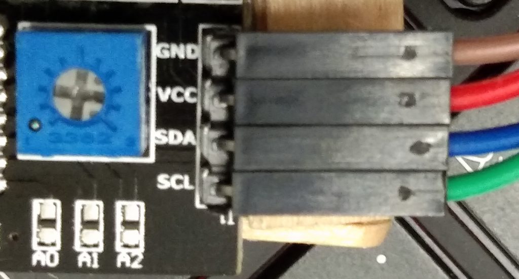
To use the PCF8574 module, the cable must be connected to a 4-pin connector that is
- VCC for 5V voltage DC power supply(because we used a 5V LCD module).
- GND for connecting to ground pin.
- SCL for connecting to the I2C bus clock pin.
- SDA for connecting to the I2C bus receiving / sending pins.
Connection
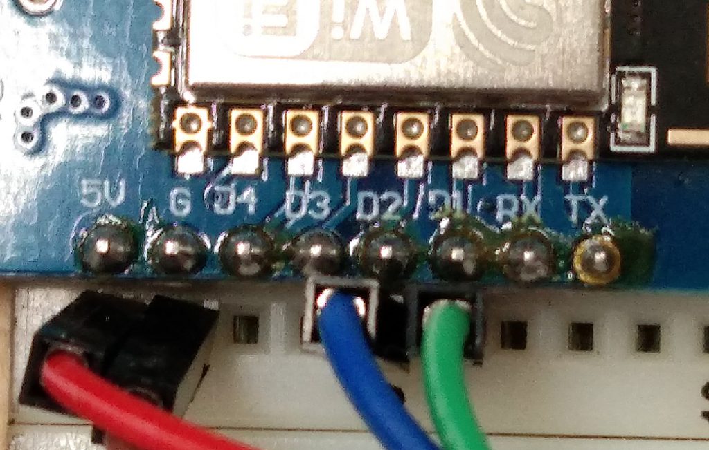
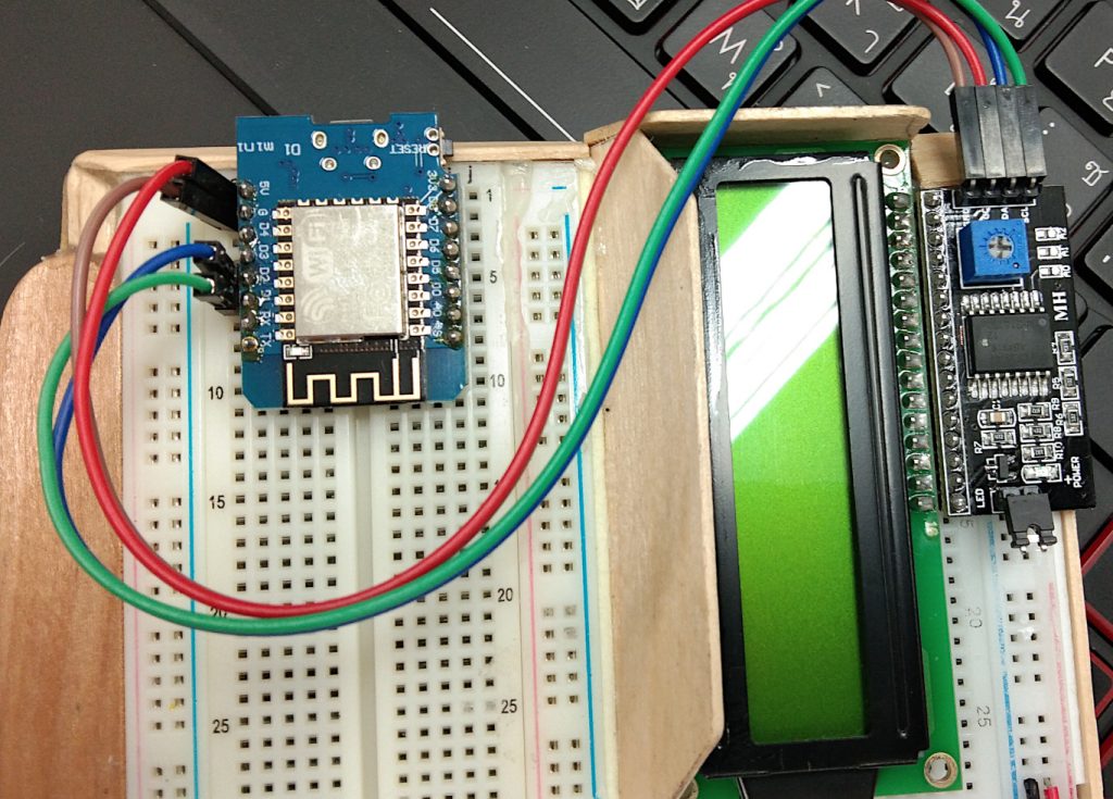
The connection between ESp8266 and PCF8574 module is as follows (see Figure 3, 4 and 5)
| ESP8266 | PCF8574 module |
|---|---|
| 5V | Vcc |
| GND | GND |
| GPIO5 (D1) | SCL |
| GPIO4 (D2) | SDA |
Library
The kjlcd.py library is an example of a python programming language to pass commands and data through the PCF8574 module to the character LCD by connecting the PCF8574 module and the LCD module as shown in Figure 2.
To use the library you need to transfer the kjlcd.py file to the ESP8266 by sending the file via Thonny or ampy.
Initialization requires a valid lcd_addr position, which we set the default position to 0x38.
The methods that can be executed are as follows.
- reset () for the LCD module to be restarted.
- write () for writing data or commands to the PCF8574 module through the I2C bus.
- cmd () for sending commands to the LCD module through the PCF8574 module via the I2C bus.
- data () for sending data to LCD module through PCF8574 module via I2C bus.
- backlight () to turn on / off the backlight LED.
- goto () for moving the display cursor’s position of the LCD module.
- putc () to display characters at cursor position.
- puts () for displaying text at the cursor position.
# JarutEx I2C Character LCD Library
import time
class LCD():
    MASK_RS = const(0x01)
    MASK_RW = const(0x02)
    MASK_E = const(0x04)
    SHIFT_BACKLIGHT = const(3)
    SHIFT_DATA = const(4)
    def __init__(self, i2c, lcd_addr=0x38):
        self.lcd_bl = True
        self.lcd_addr = lcd_addr
        self.i2c = i2c
        self.reset()
    def reset(self):
        time.sleep_ms(250)
        self.cmd(0x33)
        self.cmd(0x32)
        self.cmd(0x06)
        self.cmd(0x0C)
        self.cmd(0x28)
        self.cmd(0x01)
        time.sleep_ms(500)
        self.backlight()
    def write(self, value):
        buffer = bytearray(1)
        buffer[0] = value & 0xff
        self.i2c.writeto(self.lcd_addr, buffer)
    def cmd(self,byte):
        high_nib = (byte & 0xF0)|(self.lcd_bl << SHIFT_BACKLIGHT)
        low_nib = ((byte<<4) & 0xF0)|(self.lcd_bl << SHIFT_BACKLIGHT)
        self.write(high_nib|MASK_E)
        self.write(high_nib)
        self.write(low_nib|MASK_E)
        self.write(low_nib)
    def data(self,byte):
        high_nib = (byte & 0xF0)|MASK_RS|(self.lcd_bl << SHIFT_BACKLIGHT)
        low_nib = ((byte<<4) & 0xF0)|MASK_RS|(self.lcd_bl << SHIFT_BACKLIGHT)
        self.write(high_nib|MASK_E)
        self.write(high_nib)
        self.write(low_nib|MASK_E)
        self.write(low_nib)
    def backlight(self,status=True):
        if status:
            self.write(1<<SHIFT_BACKLIGHT)
            self.lcd_bl = True
        else:
            self.write(0)
            self.lcd_bl = False
    def goto(self,x,y):
        if y==1:
            pos = 0xC0
        else:
            pos = 0x80
        self.cmd(pos|x)
    def putc(self,ch):
        self.data(ord(ch))
    def puts(self,s):
        for idx in range(len(s)):
          self.putc(s[idx])
Example program
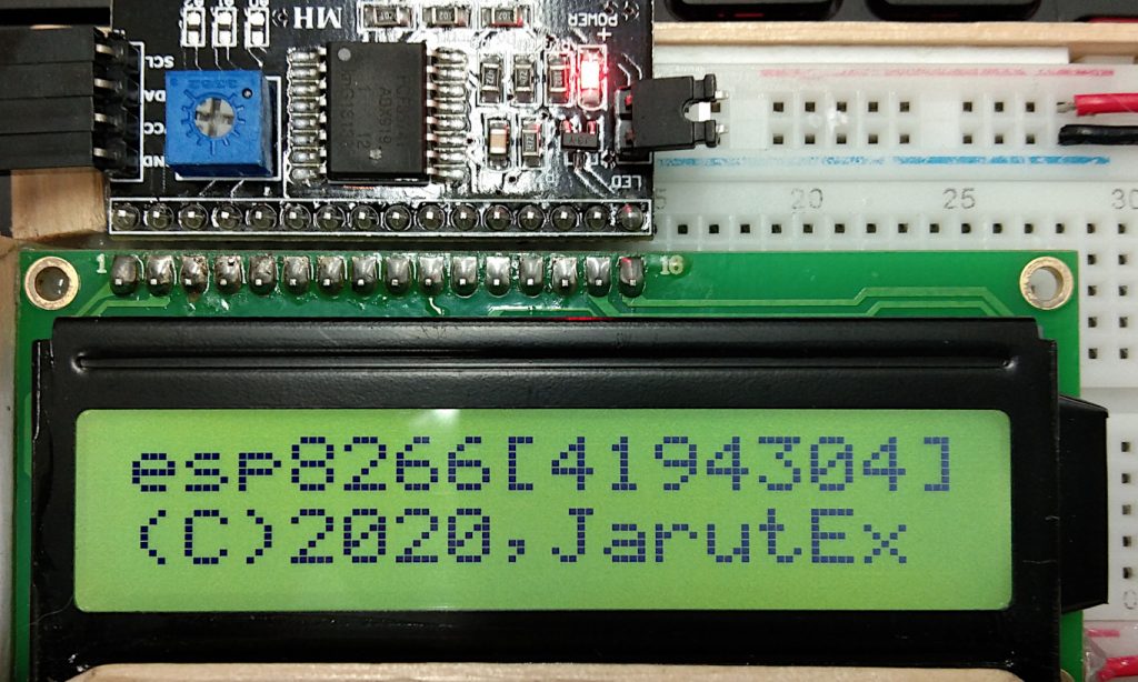
The example program code13-1 uses the kjlcd library to show the first line of text as sys.platform followed by the size of the flash ROM(esp.flash_size ()) and the second line shows text (C) 2020, JarutEx as in figure 6.
If the LCD module does not display, check the brightness by adjusting the blue variable resistor. In case of an error in the operation of the LCD library because of the data cannot be sent to the PCF8574 module, it may be due to the reverse SDA / SCL connection or the PCF8574 module position is wrong (in this example module position is 0x27), correct the position value by assigning the position value to the variable lcd_addr = const (correct position value).
# code13-1
import sys
import gc
import os
import esp
import time
import math
import machine as mc
from kjlcd import LCD
scl_pin = mc.Pin(5)
sda_pin = mc.Pin(4)
i2c = mc.I2C(scl=scl_pin,sda=sda_pin)
lcd_addr= const(0x27)
lcd = LCD(i2c,lcd_addr)
lcd.goto(0,0)
lcd.puts("{}[{}]".format(sys.platform,esp.flash_size()))
lcd.goto(0,1)
lcd.puts("(C)2020,JarutEx")
Conclusion
In this article, readers can write a python program to operate the LCD modules connected via the I2C bus and will find that their operations depend on the transmission of commands and data to the LCD module. These instructions and methods must be read from the display device documentation and adapted the instructions to send it to module PCF8574 to be read by I2C bus.
We think this article will be more or less useful for those interested in programming character LCD modules via the I2C bus and can be used to improve more functionality. As in the character LCD module, there are also various commands, such as on/off the cursor, scrolling and turning on / off the screen, etc.
Finally, have fun with programming.
(C) 2020, Jarut Busarathid and Danai Jedsadathitikul
Updated 2021-05-15