This article discusses the SPI bus functionality of the Arduino framework for use with the STM32F030F4P6, STM32F103C8, STM32F401, esp8266 and esp32. The operation of this bus requires at least 3 intercommunication cables: SCLK, MISO. and MOSI for transmitting the clock signal between the sender and the receiver. It serves to receive information from the sender. and used for sending information to the recipient.
From the use of 3 signal lines, it is found that data can be transmitted and received simultaneously. This is different from I2C bus communication that uses only one SDA cable to communicate. At the same communication speed, the SPI bus will receive and transmit data without waiting for an idle line, while I2C will have to wait for idle. With this in mind, SPI can send/receive data faster.
In addition, SPI uses a method to select the destination to communicate by instructing the endpoint to know by sending a signal to the SS pin of the terminal. Therefore, when connecting to multiple devices, SPI requires a larger number of pins to operate, while I2C uses device identification to communicate with each other by still using only one SDA cable, which saves more pins.

Pins for SPI bus
The list of pins of the SPI bus that is supported by the microcontroller hardware that we are working with is as follows.
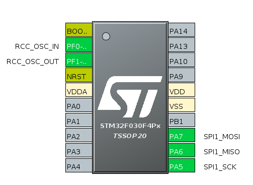
STM32F030F4P6
From Figure 1, it can be seen that this Cortex-M0 chip has 1 SPI to use via pin PA5, PA6 and PA7 for SCK, MISO and MOSI respectively. On the SS pin, select the desired GPIO_Output from the remaining pins.
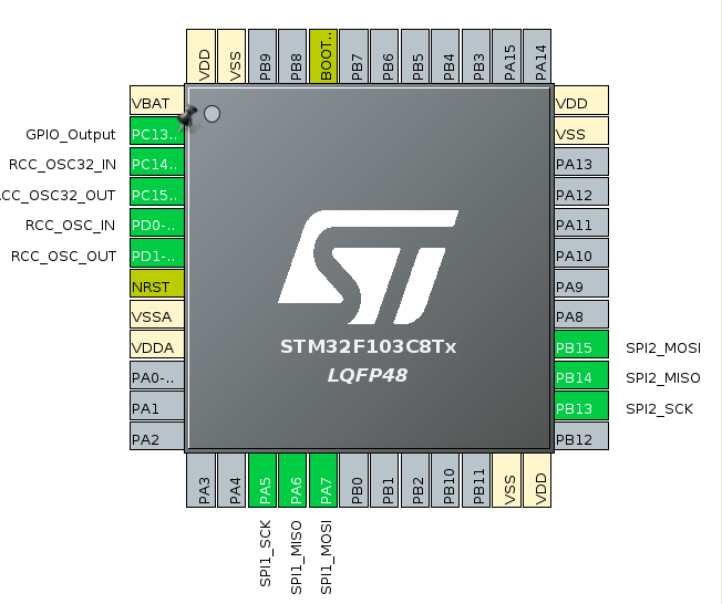
STM32F103C8
For STM32F103C8, there are 2 sets of SPI buses available, SPI1 and SPI2 that use pin PA5 and PB13 for SCK, PA6 and PB14 for MISO and PA7 and PB15 for MOSI as shown in Figure 2. The maximum speed supported is 18Mbits/second.
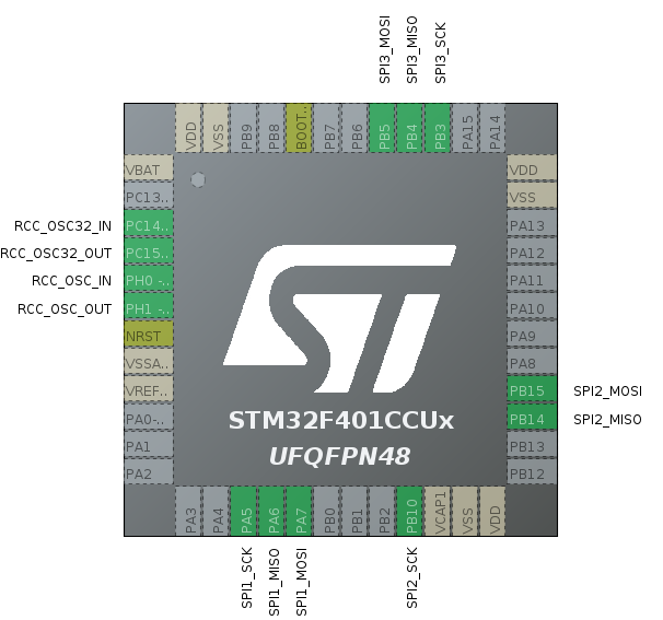
STM32F401CC
For Cortex-M4 like STM32F401CC, there is an SPI to use as shown in Figure 3. enabling SPI3 results in not being able to use I2C1, I2C2 and I2C3. And from Figure 3, pin PA5, PB10 and PB3 serve as SCK. Pin PA6, PB14 and PB4 serve as MISO, and pin PA7, PB15 and PB5 serve as MOSI of SPI1, SPI2, and SPI3, respectively.
ESP8266
The esp8266 microcontroller has one hardware SPI bus operating at up to 80MHz using the pins on the following page.
- SCLK is GPIO14
- MISO is GPIO12
- MOSI is GPIO13
ESP32
For the esp32, there are three SPI ports available, but two are available for users:
- SPI id=1 or HSPI
- SCLK is GPIO14
- MISO is GPIO12
- MOSI is GPIO13
- SPI id=2 or VSPI
- SCLK is GPIO18
- MISO is GPIO23
- MOSI is GPIO19
Instructions
Executing the SPI class must import the header file as follows:
#include <SPI.h>
To start and end an SPI class, use the begin and end commands as follows.
SPI.begin()
SPI.end()
If you want to configure the SPI bus communication, use the settings from the SPISettings( ) command to create a configuration object according to the following format. The transmission speed depends on the maximum speed set by each type of microcontroller. And there is a factor of cable quality/cable length that affects speed as well. Sort data determines how to transmit bits as MSBFIRST or LSBFIRST. Finally, data modes are SPI_MODE0, SPI_MODE1, SPI_MODE2, or SPI_MODE3.
SPISettings( max_speed, sorting, mode )
The data mode properties are according to the following table which the value affects the subject of the timing diagram.
| SPI mode | Clock polarity (CPOL/CKP) | Clock phase (CPHA) | Clock edge (CKE/NCPJA) | Output Edge | Data Capture |
|---|---|---|---|---|---|
| 0 | 0 | 0 | 1 | falling from 1 to 0 | Rising from 0 to 1 |
| 1 | 0 | 1 | 0 | Rising ช่วงเปลี่ยนจาก 0 มาเป็น 1 | falling ช่วงเปลี่ยนจาก 1 มาเป็น 0 |
| 2 | 1 | 0 | 1 | Rising from 0 to 1 | falling from 1 to 0 |
| 3 | 1 | 1 | 0 | falling from 1 to 0 | Rising from 0 to 1 |
The implementation of SPISettings is often used to initiate command communication beginTransaction() to get that setting value to set the SPI bus to start at that value as follows.
SPI.beginTransaction( SPISettings( … ) )
To end a communication transaction, use the command. endTransaction( ) as follows, which is usually called after the end of the selection of the endpoint.
SPI.endTransaction()
When initializing communication, the next step is to read or send the value to the terminal device with the transfer( ) command with the send and wait according to the following formats, which can transmit 1-byte or 2-byte data
data = SPI.transfer( data_sent )
data16 =SPI.transfer16( data_sent16 )
SPI.transferr( buffer, size )
In addition to the setting of communication via SPISettings() , the programmer can set the values from the setBitOrder, setClockDivider and setDataMode functions in the following format.
SPI.setBitOrder( sorting )
SPI.setClockDivider( clock_divider )
SPI.setDataMode( mode )
The divider are
- SPI_CLOCK_DIV2
- SPI_CLOCK_DIV4
- SPI_CLOCK_DIV8
- SPI_CLOCK_DIV16
- SPI_CLOCK_DIV32
- SPI_CLOCK_DIV64
- SPI_CLOCK_DIV128
Conclusion
From this article, it is found that using the SPI bus has more communication details than I2C and uses more wires but can receive or transmit data in both 8 and 16-bit formats, or read data as buffer chunks. The STM32 clock setting must define a divider for the ABI segment to operate at a supported frequency. If it cannot be set in the configuration step as in STM32CubeMX/IDE, let the programmer use the command setClpckDivider( ) before communicating. Finally, have fun with programming.
If you want to talk with us, feel free to leave comments below!!
References
(C) 2021, By Jarut Busarathid and Danai Jedsadathitikul
Updated 2021-11-05