We have been using the esp8266, especially the esp-01 and esp-01s modules, to manage the sensor network for quite some time and with the limitation in terms of the number of pins used, the system must be designed to work with STM32F103C8T6 or STM32F401CCU6/STM32F411CEU6. To ensure stable operation, no problems with the esp8266’s WDT were encountered, and over time, espressif released several other microcontrollers such as esp32, esp32-s2, esp32-c3 and esp32-s3.
We have tested and used esp32 almost all the time until esp32-s2 with LILYGO board made us try to order it. The main problem is that the development tools are very late. However, as of now, espressif has released a development kit for Arduino or Arduino Core for ESP32 version 2.0 with support for esp32 esp32-s2 and esp32c3, making it work with ESP32 and ESP32-S2. We got the esp-c3-32s board so this article was born.
This article is compiled from the datasheet of ESP32-C3 WROOM-02, in this article we use the board as shown in Figure 1. The example program is to drive an RGB LED on the board to work by using Arduino Core for ESP32 and the improved ESP-IDF from the article in Ep. 3

ESP32-C3
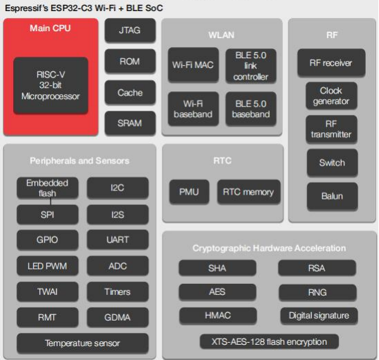
ESP32-C3 is a SoC (System on Chip), originally ESP32-C3 called ESP-C3 to replace esp8266 and has a different processor architecture, which is changed from Tensilica L106, which is a 32-bit RISC processor to 32-bit RISC-V, with both versions having the same core, one core.
Features
From the picture of the function diagram of the ESP32-C3 in Figure 2, the details of the work can be explained as follows.
- 32 bits RISC-V
- 160MHz speed from the 40MHz crystal that comes with the module.
- There are 22 GPIO pins, but 15 are usable, as the module comes with either 2 or 4MB of external flash memory (AI Thinker’s ESP-C3-32s module has a 2MB ROM).
- 400KB internal RAM memory
- Used as cache memory (Cache Memory) 16KB
- Remaining 386KB
- 8KB memory in RTC (Real-time clock) module
- Internal ROM size 384KB
- Support power saving mode.
- Support to add external flash memory.
- Connection
- Support WiFi communication.
- IEE802.11 b/g/n
- Frequency 2412 to 2484 MHz or 2.4GHz
- bandwidth 20MHz and 40MHz
- speed in 1T1R mode up to 150Mbps
- 802.11mc FTM
- Supports
- Station
- SoftAP
- Station+SoftAP
- promiscuous or mode in which the controller that controls the communication forwards all traffic received to the central processing unit. This allows package sniffing to analyze package data.
- Supports Bluetooth
- Supports Bluetooth 5 and Bluetooth mesh
- Supports 125Kbps, 500Kbps, 1Mkbps and 2Mbps
- Support WiFi communication.
- Peripherals
- GPIO
- SPI
- UART
- I2C
- I2S
- Remote Control Peripheral
- LED PWM controller
- DMA Controller
- TWAI® Controller รองรับ CAN bus
- USB Serial/JTAG controller
- Temperature sensor
- SAR
- ADC
- Conditions of use
- 3.0 ~ 3.6V
- Temperature
- –40 ~ 85 °C
- –40 ~ 105 °C
- Security that is supported at the hardware level are:
- Supports RSA-3072 secure boot, which is RSA-based encryption with a 3072-bit key.
- Supports AES-128-XTS flash memory encryption.
- Software Development
- Developed via ESP-IDF
- Developed via Arduino with Arduino core for ESP32.
- Module appearance
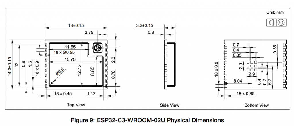
- ESP32-C3 WROOM-02 has PCB as antenna as shown Figure 3.
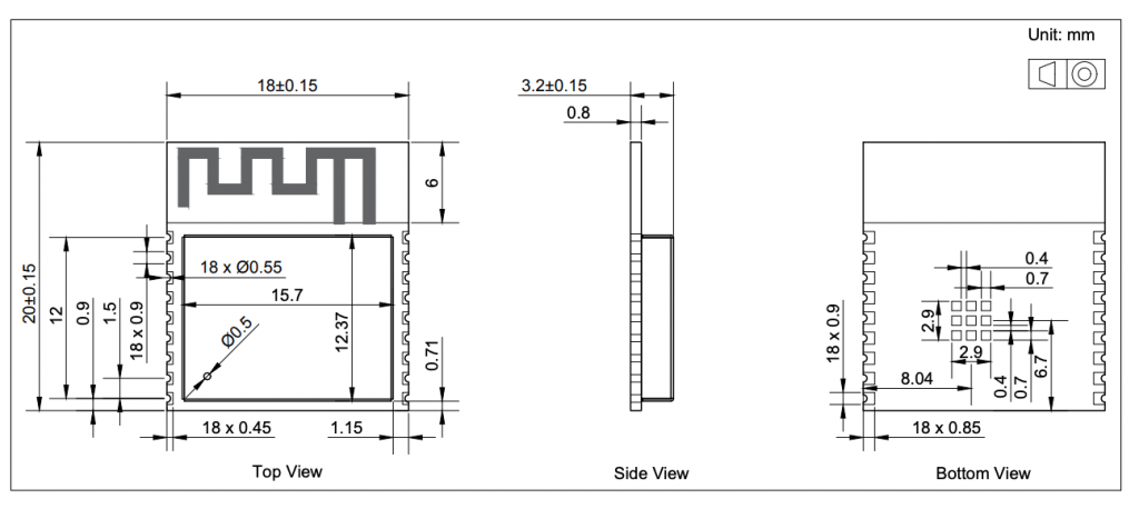
- ESP32-C3 WROOM-02U has connector for connecting antenna outside the body as shown in Figure 4.
- Implementation
- Smart Home
- Control the lighting system.
- Smart Button.
- Smart plug.
- Home Locator.
- Industrial Automation
- Industrial robots
- Mesh Network
- HMI (Human Machine Interface)
- Industrial field bus
- Health Care
- Health Monitor
- Baby Monitor
- Consumer Electronics
- Smart Watch/bracelet
- Over-the-top (OTT) devices
- WiFi and Bluetooth speaker
- Logger toys and proximity sensing toys
- Smart Agriculture
- Smart greenhouse
- Smart irrigation
- Agriculture robot
- Retail and Catering
- POS (Point-of-sell) Machine
- Service robot
- Audio Device
- Internet Music Players
- Live Streaming devices
- Internet Radio players
- Generic Low-power IoT Sensor Hubs
- Generic Low-power IoT Data Loggers
- Smart Home
From page 6 of esp-c3-32s document
From fig. 8 page 24 of ESP-32 WROOM-02 Dataheet
From fig. 9 page 24 of ESP-32 WROOM-02 Dataheet
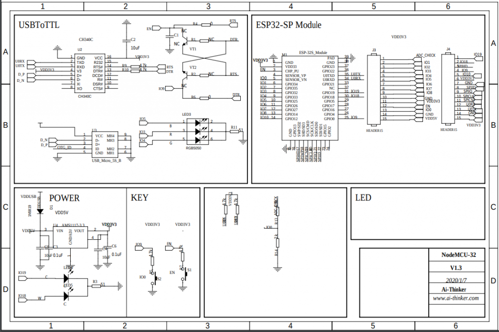
The schematic diagram of the board is shown in Figure 5, it is found that on the board there is an RGB LED that is connected to Pin IO3, IO4 and IO5 to control the emitting of red, green and blue ones.
From
GPIO
esp32-c3 has 22 pins of GPIO, which are GPIO0 to GPIO21, which have the following functions:
| GPIO | Analog Function | Note |
|---|---|---|
| GPIO0 | ADC1_CH0 | RTC, XTAL |
| GPIO1 | ADC1_CH1 | RTC, XTAL |
| GPIO2 | ADC1_CH2 | Strapping pin, RTC, FSPIQ |
| GPIO3 | ADC1_CH3 | RTC, connect to red LED |
| GPIO4 | ADC1_CH4 | RTC, connect to green LED, FSPIHD, MTMS |
| GPIO5 | ADC2_CH0 | RTC, connect to blue LED usable in Deep Sleep, FSPIWP, MTDI |
| GPIO6 | FSPICLK, MTCK | |
| GPIO7 | FSPID, MTD0 | |
| GPIO8 | Strapping pin | |
| GPIO9 | Strapping pin | |
| GPIO10 | FSPICS0 | |
| GPIO11 | ||
| GPIO12 | SPIO/1 use with SPI Flash and PSRAM shouldn’t be used | |
| GPIO13 | SPIO/1 use with SPI Flash and PSRAM shouldn’t be used | |
| GPIO14 | SPIO/1 use with SPI Flash and PSRAM shouldn’t be used | |
| GPIO15 | SPIO/1 use with SPI Flash and PSRAM shouldn’t be used | |
| GPIO16 | SPIO/1 use with SPI Flash and PSRAM shouldn’t be used | |
| GPIO17 | SPIO/1 use with SPI Flash and PSRAM shouldn’t be used | |
| GPIO18 | USB-JTAG if use as GPIO, USB-JTAG will unavailable | |
| GPIO19 | USB-JTAG if use as GPIO, USB-JTAG will unavailable | |
| GPIO20 | RX0 | |
| GPIO21 | TX0 |
Installation
Installing the Arduino core for ESP32 kit is done by defining the following json in File/Preferences.
https://raw.githubusercontent.com/espressif/arduino-esp32/gh-pages/package_esp32_index.json
after that go to Tools/Board…/Boards Manager, select esp32 and install, you will get Arduino core for ESP32 development kit in your machine.
Configuration
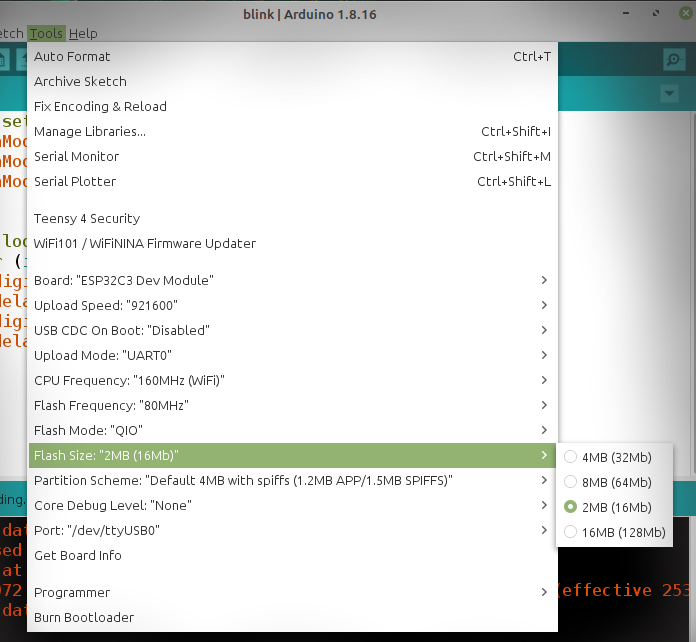
The configuration for Ai Thinker esp-c3-32s modules must set the Flash size to 2MB as shown in Figure 5.
Example Code
An example of programming to control the LED that comes with the microcontroller board to be installed is as follows.
void setup() {
pinMode(3, OUTPUT);
pinMode(4, OUTPUT);
pinMode(5, OUTPUT);
}
void loop() {
for (int i = 3; i < 6; i++) {
digitalWrite(i, LOW);
delay(250);
digitalWrite(i, HIGH);
delay(250);
}
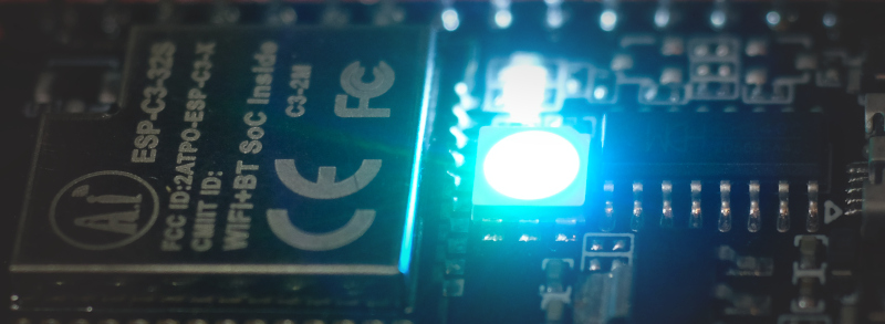
}From the code, it can be found that the pins used to communicate with the RGB LEDs on the board are pins 3, 4 and 5 that are connected to pins LED_R, LED_G and LED_B. To drive the LED on, you must send a digital signal 1, because this causes the pin to have voltage on the pin connected to the LED and the other pin of the LED to be connected to GND, thus completing the current flow through it, causing the LED to light up. The example picture of the work is shown in Figure 7.
The code for the ESP-IDF modified from the article ESP-IDF Ep.3 : GPIO Output is as follows.
#include <stdio.h>
#include <time.h>
#include <string.h>
#include <math.h>
#include "driver/gpio.h"
#include "sdkconfig.h"
#include "freertos/FreeRTOS.h"
#include "freertos/task.h"

#define LED_R_PIN 3
#define LED_G_PIN 4
#define LED_B_PIN 5

void app_main(void)
{
  printf("C3 LEDs");
  gpio_pad_select_gpio(LED_R_PIN);
  gpio_set_direction(LED_R_PIN, GPIO_MODE_OUTPUT);
  gpio_pad_select_gpio(LED_G_PIN);
  gpio_set_direction(LED_G_PIN, GPIO_MODE_OUTPUT);
  gpio_pad_select_gpio(LED_B_PIN);
  gpio_set_direction(LED_B_PIN, GPIO_MODE_OUTPUT);

  while(1) {
    gpio_set_level(LED_R_PIN, 1);
    vTaskDelay( 500/portTICK_PERIOD_MS );
    gpio_set_level(LED_R_PIN, 0 );
    vTaskDelay( 500/portTICK_PERIOD_MS );
    gpio_set_level(LED_G_PIN, 1);
    vTaskDelay( 500/portTICK_PERIOD_MS );
    gpio_set_level(LED_G_PIN, 0 );
    vTaskDelay( 500/portTICK_PERIOD_MS );
    gpio_set_level(LED_B_PIN, 1);
    vTaskDelay( 500/portTICK_PERIOD_MS );
    gpio_set_level(LED_B_PIN, 0 );
    vTaskDelay( 500/portTICK_PERIOD_MS );
    gpio_set_level(LED_R_PIN, 1 );
    gpio_set_level(LED_G_PIN, 1 );
    gpio_set_level(LED_B_PIN, 0 );
    vTaskDelay( 500/portTICK_PERIOD_MS );
    gpio_set_level(LED_R_PIN, 0 );
    gpio_set_level(LED_G_PIN, 1 );
    gpio_set_level(LED_B_PIN, 1 );
    vTaskDelay( 500/portTICK_PERIOD_MS );
    gpio_set_level(LED_R_PIN, 1 );
    gpio_set_level(LED_G_PIN, 0 );
    gpio_set_level(LED_B_PIN, 1 );
    vTaskDelay( 500/portTICK_PERIOD_MS );
    gpio_set_level(LED_R_PIN, 1 );
    gpio_set_level(LED_G_PIN, 1 );
    gpio_set_level(LED_B_PIN, 1 );
    vTaskDelay( 500/portTICK_PERIOD_MS );
    gpio_set_level(LED_R_PIN, 0 );
    gpio_set_level(LED_G_PIN, 0 );
    gpio_set_level(LED_B_PIN, 0 );
    vTaskDelay( 500/portTICK_PERIOD_MS );
  }
}
Conclusion
From this article, it will be found that the ESP32-C3 is a new alternative to espressif that decided to try the market by using RISC-V as a central processor and we also found its best development tool is still espressif’s ESP-IDF due to its complete functionality and update to fix problems faster than the Arduino core for ESP32, which is normal. Because the upstream must be stable before the downstream will be changed. Finally, have fun with programming.
If you want to talk with us, feel free to leave comments below!!
References
(C) 2020-2021, By Jarut Busarathid and Danai Jedsadathitikul
Updated 2021-12-20