This article discusses the use of the ESP32’s GPIO as an analog input. By using the voltage input circuit from adjusting values with an adjustable resistor as shown in Figure 1. So, in this article, we will learn how to use the ADC instruction of the ESP32 microcontroller and how to configure the value of ADC in menuconfig.

Project structure
The structure of the ESP-IDF project is as shown in Figure 2. In the project directory, there are files CMakeList.txt and sdkconfig with a directory named main to store the project source code. The directory contains the C language files and CMakeLists.txt.

From the structure in Figure 2, the CMakeLists.txt file’s code must be generated as follows, in which the code content defines the minimum version of cmake program and configures the default cmake implementation according to the original ESP-IDF and named the project as ep06.
cmake_minimum_required(VERSION 3.5)
include($ENV{IDF_PATH}/tools/cmake/project.cmake)
project(ep06)
What writes main/CMakeLists.txt is as follows to define a list of files to be compiled. This is defined as main.c and sets the directory where the header file is stored, meaning it is either the same as main.c or in the main directory.
idf_component_register(SRCS "main.c"
                    INCLUDE_DIRS "")
When creating a structure like Figure 2, select the target of the system to be ESP32 as follows:
idf.py set-target esp32
The sdkconfig is created by running the following command idf.py menuconfig.
idf.py menuconfig
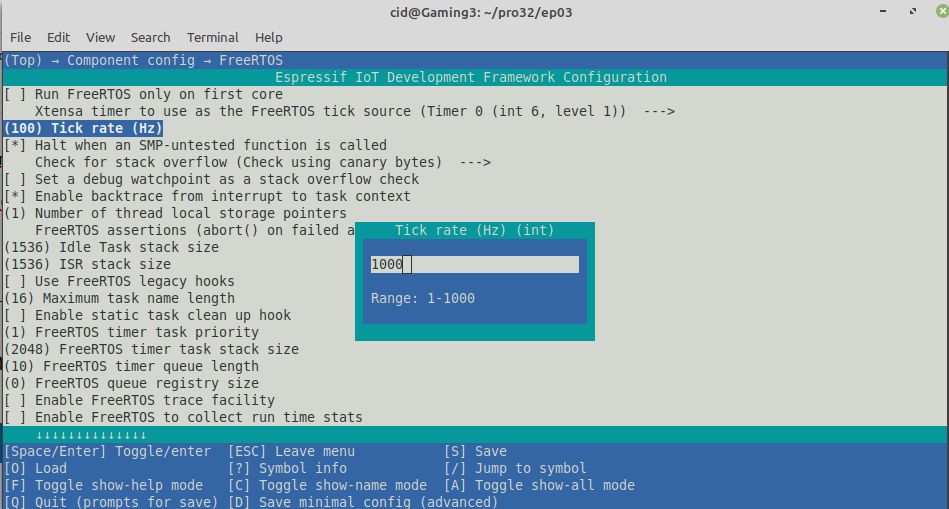
From the configuration screen, go to Component Config –> FreeRTOS and set the tick rate (Hz) to 1000 as shown in Figure 3, then save and exit the settings.
For ADC settings, go to Component config and select ADC-Calibration. Check if (*) all 3 options are selected as shown in Figure 4. After that, press S to save and Q to exit the setup screen.

ADC Usage
The ESP32 microcontroller has a 3V3 voltage converter circuit to a digital value with a resolution of 12 bits, enabling the conversion from 0 to 3v3 to 0 to 4095 or 4096 levels, and has two ADC sectors called ADC1 and ADC2 where
- ADC1 has 8 channels via pins 32, 33, 34, 35, 36, 37, 38 and 39.
- ADC2 has 10 channels via pins 0, 2, 4, 12, 13, 14, 15, 25, 26 and 27.
But when the programmer uses the WiFi sector, the ADC2 of the specified pin is invalid. Because the ADC2 sector is used to convert the signal of the WiFi circuit but the pins in the ADC2 sector can still work digitally or make a DAC (pins 25, 26 and 27). Therefore, this article focuses mainly on the use of ADC1.
On the ESP32 DevKit board, pin 0 is not available due to being programmed into the chip and the board ESP-WROVER-KIT Pins 0,2,4 and 15 cannot be used because they are used in the chip circuit, and 2,4,15 are connected to SPI RAM or other auxiliary circuits that are added outside of a regular ESP32 module.
And if the circuit is not connected to the ADC pin, the value of the pin will be a random number. It is therefore useful to use it as a default random value.
The ADC implementation must import the header file as follows:
#include <driver/adc.h>
Commands
Using the ADC, the resolution of the conversion can be specified with the command adc1_config_width() in the following format which can allow conversion because conversions at lower resolutions result in faster performance. And some systems may not want to recognize a high resolution in exchange for the speed of response, etc.
adc1_config_width( bit )
The bit count is a constant representing the configurable conversion resolution: 9, 10, 11, and 12 bits.
- ADC_WIDTH_BIT_9
- ADC_WIDTH_BIT_10
- ADC_WIDTH_BIT_11
- ADC_WIDTH_BIT_12
In addition, the attenuation value of the input voltage can be adjusted to support multi-level pressure conversion by command:
adc1_config_channel_atten(ch, attenuation)
The attenuation values are as follows:
- ADC_ATTEN_DB_0 to support the operation of voltages up to 800mV.
- ADC_ATTEN_DB_2_5 to support operation of approximately 0 to 1.1VDC (1.33x) voltage.
- ADC_ATTEN_DB_6 to support operation of approximately 0 to 2.2VDC (2x) voltage.
- ADC_ATTEN_DB_11 to support operation of approximately 0 to 3.3VDC (3.55x) voltage
The value of the channel number is as follows.
- ADC1_CHANNEL_0 for pin 36
- ADC1_CHANNEL_1 for pin 37
- ADC1_CHANNEL_2 for pin 38
- ADC1_CHANNEL_3 for pin 39
- ADC1_CHANNEL_4 for pin 32
- ADC1_CHANNEL_5 for pin 33
- ADC1_CHANNEL_6 for pin 34
- ADC1_CHANNEL_7 for pin 35
For importing analog data into digital, use the command adc1_get_raw() according to the following usage patterns.
digital = adc1_get_raw( ch )
If you want to use other GPIOs, you can read more articles as follows.
Conversion
To calculate the voltage from a digital value, use the following equation:
voltage = (float)((dValue/4095.0f)*3.3f)
can be written as a function that converts values according to the function dValueToVolt()
float dValueToVolt( int dValue )
{
    return (float)((dValue/4096.0f)*3.3f);
}
Example Code
The LED circuit used in this experiment is shown in Figure 5. The devices used in the experiment are:
- esp32
- Experiment board
- Adjustable resister

Code
#include <stdio.h>
#include <time.h>
#include <string.h>
#include <math.h>
#include <driver/adc.h>
#include "driver/gpio.h"
#include "sdkconfig.h"
#include "freertos/FreeRTOS.h"
#include "freertos/task.h"

#define pinADC ADC1_CHANNEL_0 // GPIO36

float dValueToVolt( int dValue )
{
    return (float)((dValue/4096.0f)*3.3f);
}

void app_main(void)
{
  int dValue = 0;
  float volt = 0.0;

  printf("Ep.06 ADC\n");
  adc1_config_width( ADC_WIDTH_BIT_12 );
  adc1_config_channel_atten( pinADC, ADC_ATTEN_DB_11);

  while(1) {
    dValue = adc1_get_raw( pinADC );
    volt = dValueToVolt( dValue );
    printf("dValue = %d, V = %.2f\n",
      dValue, volt);
    vTaskDelay( 250/portTICK_PERIOD_MS );
  }
}
Compile and upload
Compile, then flash it into the chip and run the Serial Monitor program as follows:
idf.py -p /dev/ttyUSB0 build flash monitor
An example of the program results displayed will be shown in Figure 6.

Conclusion
From this article, you will find that There are 3 steps for importing analog signals:
- Configure the resolution of the conversion with the command adc1_config_width()
- Configure the attenuation of the input voltage to the analog input with the adc1_config_channel_atten() command.
- Reading the value from the pin defined by the command adc1_get_raw()
Finally, have fun with programming.
If you want to talk with us, feel free to leave comments below!!!
Reference
- ESP-IDF : ADC
(C) 2020-2021, By Jarut Busarathid and Danai Jedsadathitikul
Updated 2021-12-28