This article discusses the implementation of a servo motor module using the ESP32’s GPIO that outputs a digital PWM signal or Pulse Width Modulation or an LEDC (LED Control) which enables frequency band generation or adjust the proportion of status 1 and 0 in 1 waveform with a frequency of 50Hz using the experimental board as shown in Figure 1.

Project structure
The structure of the ESP-IDF project is as shown in Figure 2. In the project directory there are files CMakeList.txt and sdkconfig with a directory named main to store the project source code. The directory contains the C language files and CMakeLists.txt.

From the structure in Figure 2, the CMakeLists.txt file’s code must be generated as follows, in which the code content defines the minimum version of cmake program and configures the default cmake implementation according to the original ESP-IDF and names the project as ep10.
cmake_minimum_required(VERSION 3.5)
include($ENV{IDF_PATH}/tools/cmake/project.cmake)
project(ep10)
What is written in the file main/CMakeLists.txt is as follows to define a list of files to be compiled. This is defined as main.c and sets the directory where the header files are stored, meaning the same place as main.c or in the main directory.
idf_component_register(SRCS "main.c"
                    INCLUDE_DIRS "")
When creating a structure like Figure 2, select the target of the system to be ESP32 as follows:
idf.py set-target esp32
The sdkconfig is created by running the following command idf.py menuconfig.
idf.py menuconfig
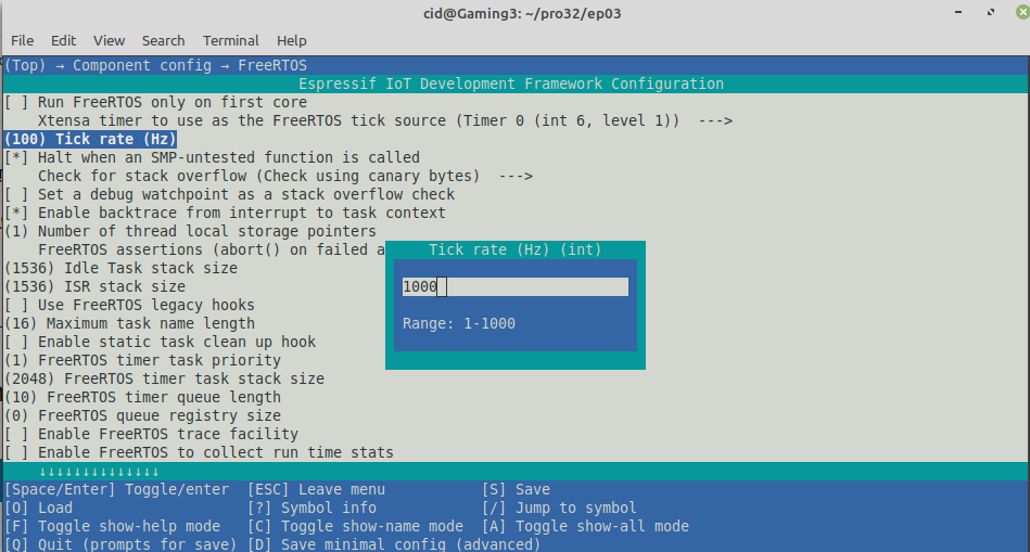
From the configuration screen, go to Component Config –> FreeRTOS and set the tick rate (Hz) to 1000 as shown in Figure 3, then save and exit the settings.
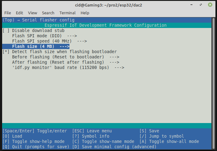
What is often forgotten is to set the capacity of the ROM memory (Flash size) as shown in Figure 4 to match the size installed on the board from the Serial flasher config, which in the article is 4MB. After that, press S and Q to save and exit the settings.
Servo motor
A servo motor is a small DC electric motor. The set consists of a DC electric motor and a gear drive. It does not use much current but has high torque and is lightweight. By controlling this type of electric motor, the motor can be rotated to the far left angle or the right end of the motor. Each of them has different values. Therefore, we can order the motor to rotate 0 degrees, 90 degrees and 180 degrees as shown in Figures 5, 6 and 7, respectively.


Connecting the wires from the servo motor to the test board in Figure 1 is done as follows.
- Black wire to GND
- Red wire to 3V3
- Orange wire to pin 22
The use of an LEDC or PWM with a servo motor requires that the frequency of the waveform be equal to 50Hz, so it must be configured as follows.
  ledc_timer_config_t ledc_timer = {
        .speed_mode       = LEDC_LOW_SPEED_MODE,
        .timer_num        = LEDC_TIMER_0,
        .duty_resolution  = LEDC_TIMER_13_BIT,
        .freq_hz          = 50,
        .clk_cfg          = LEDC_AUTO_CLK
  };
and set duty in ledc_set_duty() and run it with command ledc_update_duty() as follows:
  ledc_set_duty(LEDC_LOW_SPEED_MODE, LEDC_CHANNEL_0, duty);
  ledc_update_duty(LEDC_LOW_SPEED_MODE, LEDC_CHANNEL_0);
As for the calculation of duty, which is an integer value that represents the percentage of the voltage state 1 to 1 waveform with a value of 13 bits (as defined by duty_resolution), or a number in the range 0 to 213 (or a decimal number 8,191).
Motor movement is usually fixed so that it can be rotated to the left-end and the right-end which has a different value but it can be changed to be able to rotate 360 degrees as well. However, in this article, we would like to talk about controlling a motor that rotates normally. Therefore, the operation is ordered with the minimum duty value, making it turn to the left-end and the right-end. Therefore, in the program, there are 3 constants: 0 degrees, 180 degrees, and 90 degrees (middle between 0 and 180 degrees), as follows:
- ServoMsMin, the minimum value that causes the rotation to be 0 degrees.
- ServoMsMax , the maximum value that causes the rotation to be 180 degrees.
- ServoMsAvg ((ServoMsMax-ServoMsMin)/2.0)
With the need to set the transmission frequency to be 50Hz, making each wave have a length or value equal to the following values:
T = 1/f
= 1/50
Therefore, T is equal to 20ms.
When we know the values of ServoMsMin, ServoMsAvg and ServoMsMax, which are milliseconds, by looking at all three values as t1, or the time interval with the status of 1, we get that
T = t0+t1
t0 = T-t1
And with T at 0% being 0 and 100% being 8191, we get that each 1% is 81.91. Our task is to find out what percentage of t t1 is:
percentage of t1 = 100*t1/20
From finding the value, the duty value is calculated as follows:
int duty = (int)(100.0*(t1/20.0)*81.91);If you want to use other GPIOs, you can read more articles as follows.
Example Code
Example program to generate 50Hz frequency to send servo motor connected to GPIO22 pin by sending duty values for ordering it to move 0 degrees, 90 degrees, 180 degrees, and 90 degrees and stop for 2 seconds each time and keep looping, causing the motor to rotate at 0, 90, 180 and 90 degrees, and show the result as shown in Figure 8, which all code can be written as follows
#include <stdio.h>
#include <time.h>
#include <string.h>
#include <math.h>
#include <sdkconfig.h>
#include <driver/gpio.h>
#include <driver/ledc.h>
#include <freertos/FreeRTOS.h>
#include <freertos/task.h>

#define pinServo 22
#define ServoMsMin 0.06
#define ServoMsMax 2.1
#define ServoMsAvg ((ServoMsMax-ServoMsMin)/2.0)

void servoDeg0() {
  ledc_timer_config_t ledc_timer = {
        .speed_mode       = LEDC_LOW_SPEED_MODE,
        .timer_num        = LEDC_TIMER_0,
        .duty_resolution  = LEDC_TIMER_13_BIT,
        .freq_hz          = 50,
        .clk_cfg          = LEDC_AUTO_CLK
  };
  ledc_timer_config(&ledc_timer);
  ledc_channel_config_t ledc_channel = {
        .speed_mode     = LEDC_LOW_SPEED_MODE,
        .channel        = LEDC_CHANNEL_0,
        .timer_sel      = LEDC_TIMER_0,
        .intr_type      = LEDC_INTR_DISABLE,
        .gpio_num       = pinServo,
        .duty           = 0,
        .hpoint         = 0
  };
  ledc_channel_config(&ledc_channel);
  int duty = (int)(100.0*(ServoMsMin/20.0)*81.91);
  printf("%fms, duty = %f%% -> %d\n",ServoMsMin, 100.0*(ServoMsMin/20.0), duty);
  ledc_set_duty(LEDC_LOW_SPEED_MODE, LEDC_CHANNEL_0, duty);
  ledc_update_duty(LEDC_LOW_SPEED_MODE, LEDC_CHANNEL_0);
  vTaskDelay( 2000/portTICK_PERIOD_MS );
  ledc_stop(LEDC_LOW_SPEED_MODE, LEDC_CHANNEL_0, 0);
}

void servoDeg90() {
  ledc_timer_config_t ledc_timer = {
        .speed_mode       = LEDC_LOW_SPEED_MODE,
        .timer_num        = LEDC_TIMER_0,
        .duty_resolution  = LEDC_TIMER_13_BIT,
        .freq_hz          = 50,
        .clk_cfg          = LEDC_AUTO_CLK
  };
  ledc_timer_config(&ledc_timer);
  ledc_channel_config_t ledc_channel = {
        .speed_mode     = LEDC_LOW_SPEED_MODE,
        .channel        = LEDC_CHANNEL_0,
        .timer_sel      = LEDC_TIMER_0,
        .intr_type      = LEDC_INTR_DISABLE,
        .gpio_num       = pinServo,
        .duty           = 0,
        .hpoint         = 0
  };
  ledc_channel_config(&ledc_channel);
  int duty = (int)(100.0*(ServoMsAvg/20.0)*81.91);
  printf("%fms, duty = %f%% -> %d\n",ServoMsAvg, 100.0*(ServoMsAvg/20.0), duty);
  ledc_set_duty(LEDC_LOW_SPEED_MODE, LEDC_CHANNEL_0, duty);
  ledc_update_duty(LEDC_LOW_SPEED_MODE, LEDC_CHANNEL_0);
  vTaskDelay( 2000/portTICK_PERIOD_MS );
  ledc_stop(LEDC_LOW_SPEED_MODE, LEDC_CHANNEL_0, 0);
}

void servoDeg180() {
  ledc_timer_config_t ledc_timer = {
        .speed_mode       = LEDC_LOW_SPEED_MODE,
        .timer_num        = LEDC_TIMER_0,
        .duty_resolution  = LEDC_TIMER_13_BIT,
        .freq_hz          = 50,
        .clk_cfg          = LEDC_AUTO_CLK
  };
  ledc_timer_config(&ledc_timer);
  ledc_channel_config_t ledc_channel = {
        .speed_mode     = LEDC_LOW_SPEED_MODE,
        .channel        = LEDC_CHANNEL_0,
        .timer_sel      = LEDC_TIMER_0,
        .intr_type      = LEDC_INTR_DISABLE,
        .gpio_num       = pinServo,
        .duty           = 0,
        .hpoint         = 0
  };
  ledc_channel_config(&ledc_channel);
  int duty = (int)(100.0*(ServoMsMax/20.0)*81.91);
  printf("%fms, duty = %f%% -> %d\n",ServoMsMax, 100.0*(ServoMsMax/20.0), duty);
  ledc_set_duty(LEDC_LOW_SPEED_MODE, LEDC_CHANNEL_0, duty);
  ledc_update_duty(LEDC_LOW_SPEED_MODE, LEDC_CHANNEL_0);
  vTaskDelay( 2000/portTICK_PERIOD_MS );
  ledc_stop(LEDC_LOW_SPEED_MODE, LEDC_CHANNEL_0, 0);
}

void manualServo() {
  printf("  0 degree:");
  servoDeg0();
  printf(" 90 degree:");
  servoDeg90();
  printf("180 degree:");
  servoDeg180();
  printf(" 90 degree:");
  servoDeg90();
}

void app_main(void)
{
  printf("EP10 : LEDC&Servo Motor\n");
  while (1) {
    manualServo();
  }
}
Compile and upload
Compile, then flash it into the chip and run the Serial Monitor program as follows:
idf.py -p /dev/ttyUSB0 build flash monitor
An example of the program output is shown in Figure 8.

Conclusion
From this article, you will find that the use of PWM or LEDC consists of 3 steps:
- Set the timer with ledc_timer_config()
- Channel setting with ledc_channel_config()
- Control with ledc_set_duty(), ledc_update_duty() และ ledc_stop()
However, Using this example, we need to change the values of ServoMsMin and ServoMsMax accordingly to make the motor rotate to the correct position as shown in Figures 5, 6 and 7. From both articles, we can see that we can use LEDC or PWM to control both dim/light the brightness of the LED, transmitting frequencies to the speaker, and control the direction of the servo motor by using the same command but different methods must be applied according to the peripheral devices. Therefore, it is important to practice writing and understanding the device in practice. And finally, have fun with programming.
If you want to talk with us, feel free to leave comments below!!!
References
- WiKiPedia : Pulse-width modulation
- ESP-IDF : LEDC
(C) 2020-2021, By Jarut Busarathid and Danai Jedsadathitikul
Updated 2022-01-02