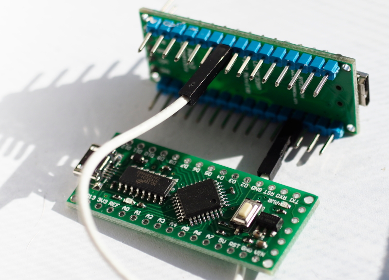
This article is a continuation of the previous article introducing the LGT8F328P board and its use of ADC and DAC. By focusing on the use for the chip LGT8F328P, which is different from the SAM-D21 in that it uses pin D4 as a pin that serves as DAC0 and the DAC circuit has a resolution of 8-bit. The output can be from 0 to 255. The ADC sector uses pins A0, A1, … normally and has a resolution of 12 bits. Therefore, in this article, the connection pins from A0 to D4 are used in the experiment as shown in Figure 1.
Instruction
The instructions for using the ADC and DAC are as follows.
DAC pin
The command to set the DAC0 pin to work in analog can be used as follows.
pinMode(DAC0, ANALOG);
ADC resolution
Instructions for adjusting the ADC resolution of the LGT8F328P microcontroller are used as follows, where x is the number of bits in operation.
analogReadResolution( x )
ADC reading
The LGT8F328P chip’s ADC readout format uses the analogRead( ) command with the PIN to be read. The pins are A0, A1, A2, A3, 4, A5, A6 and A7.
data = analogRead( pin )
DAC output data command
For the LGT8F328P’s 8-bit data output instruction, the following format can be used by specifying the pin as D4 or DAC0.
analogWrite( pin, output )
The command defines the reference voltage pin.
In cases where a reference voltage source is required for analog operation, the reference source can be specified from the command analogReference() by defining reference x in the following format:
analogReference( x )
จwhere x as
- DEFAULT , uses 5V.
- EXTERNAL , use the REF pin as the reference voltage source input.
- INTERNAL4V096 , uses a 4.096v reference voltage from inside the board.
- INTERNAL2V048 , uses a 2.048v reference voltage from inside the board.
- INTERNAL1V048 , uses a 1.048v reference voltage from inside the board.
Example Code
Examples of 3 types of graph drawing programs are zigzag, triangular and sine wave graph, there is working code as follows:
Zigzag graph
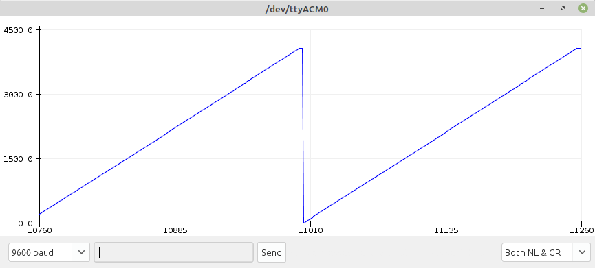
The zigzag graph is transmitted 0 to the maximum possible value of the DAC sector, after which it loops through again. The code for LGT8F328P is as follows, and the result is shown in Figure 2. We found that on some boards it gives the wrong result as shown in Figure 3. So before actual use, you should check the chip’s functionality first.
#include <Arduino.h>

#define pinSpk DAC0 // D4
#define pinMic A0
#define MAX_VALUE 255
#define ADC_BITS 12

int adcValue;

void setup() {
  Serial.begin(9600);
  analogReadResolution(ADC_BITS);
  analogReference(DEFAULT);  // 5v
  pinMode(DAC0, ANALOG);
}

void loop() {
  for (int i = 0; i < MAX_VALUE+1; i ++) {
    analogWrite( pinSpk, i);
    adcValue = analogRead(pinMic);
    Serial.println(adcValue);
  }
}

Triangular graph
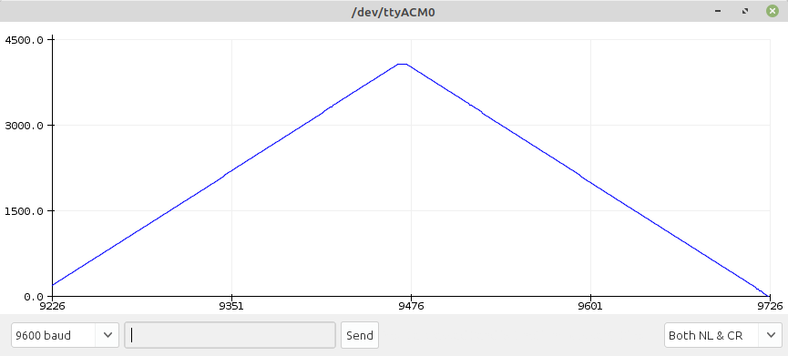
The triangular graph works similarly to the zigzag principle by adding a loop to return the maximum value to 0 as shown in the LGT8F328P code as follows, and the resulting example is shown in Figure 4.
#include <Arduino.h>

#define pinSpk DAC0 // D4
#define pinMic A0
#define MAX_VALUE 255
#define ADC_BITS 12

int adcValue;

void setup() {
  Serial.begin(9600);
  analogReadResolution(ADC_BITS);
  analogReference(DEFAULT);  // 5v
  pinMode(DAC0, ANALOG);
}

void loop() {
  int i;
  for (i = 0; i < MAX_VALUE+1; i ++) {
    analogWrite( pinSpk, i);
    adcValue = analogRead(pinMic);
    Serial.println(adcValue);
  }
  for (i = MAX_VALUE-1; i >= 0; i--) {
    analogWrite( pinSpk, i);
    adcValue = analogRead(pinMic);
    Serial.println(adcValue);
  }
}
Sine wave graph
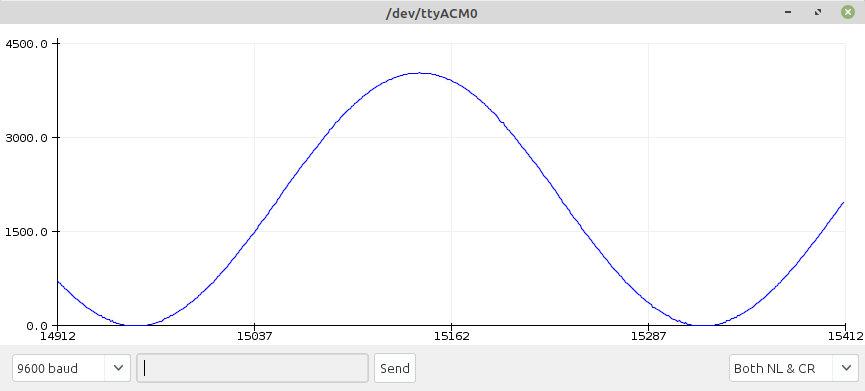
Constructing a sinusoidal wave graph uses a loop designation to increase the degree angle from 0 to 359, with each cycle doing the following:
- Convert degrees to radians.
- Calculate the sine from the radian angle.
- Converts decimal values to integers in the value range supported by the DAC.
- Read the value from the ADC.
- Send data through serial port to program Serial Plotter.
The code for LGT8F328P is as follows, and the example output is shown in Figure 5.
#include <Arduino.h>

#define pinSpk DAC0 // D4
#define pinMic A0
#define MAX_VALUE 255
#define ADC_BITS 12

int adcValue;

void setup() {
  Serial.begin(9600);
  analogReadResolution(ADC_BITS);
  analogReference(DEFAULT);  // 5v
  pinMode(DAC0, ANALOG);
}

void loop() {
  int degree = 0;
  float radian = 0.0;
  float sineValue = 0.0;
  int dValue = 0;

  for (degree = 0; degree < 360; degree++) {
    radian = (float)degree * (2.0 * 3.1415926) / 360.0;
    sineValue = sin(radian);
    dValue = (int)((1.0 + sineValue) * 125.0);
    analogWrite( pinSpk, dValue );
    adcValue = analogRead(pinMic);
    Serial.println(adcValue);
  }
}
Conclusion
From this article, the LGT8F328P’s ADC is fairly linear. But the we found that many boards that we ordered have more noise than usual. And some boards don’t work in the case of sine wave graphs. The DAC has 8-bit resolution, which is the same resolution as esp32, but at a lower cost than both the SAM-D21 and ESP32, the LGT8F328P looks attractive to implementation because at least it has more ADC pins than SAM-D21. Finally, have fun programming.
(C) 2020-2022, By Jarut Busarathid and Danai Jedsadathitikul
Updated 2022-01-25