[EN] PIC18F458 Ep.6 ADC

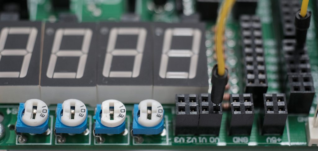
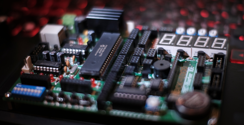
This article uses the GPIO of the PIC18F458 microcontroller connected to an ADC module or an analog-to-digital converter module for reading voltage levels in the 0 to 5V range from the input signal. This allows the system designer to consider the details of the voltage from the circuit, such as from the variable resistor, resistors change their values ​​according to the brightness or microphone values, for example, to process these values or enter the next working condition, such as reading the voltage to report the result as a voltage in the Lo, Hi or unstable level, etc. On the computer architecture experiment board, there are 4 sets of adjustable resistor circuits as shown in Figure 1 makes it possible to study programming to use the ADC module and be able to apply it in the future.

Figure 1 ADC module on the board
Read More

[EN] PIC18F458 Ep.5 GPIO and 7-Segments

This article is the application of GPIO of PIC18F458 to operate the circuit of 8 LEDs arranged in the same position as the numbers shown in Figure 1 by using 8 LED to be rearranged and called 7-Segment that can be applied to display numbers and another number of characters. In addition, the experimental board has installed a 7-Segment of 4 digits, allowing you to write a program to control the display of 4 digits of data.

Figure 1 Display on 7-Segment
Read More

[EN] PIC18F458 Ep.3 An Introduction to Using MPLAB X IDE with XC8.

This article uses the MPLAB X IDE development kit (Figure 1) for use with Microchip’s 8-bit microcontrollers in C language through a translation tool called XC8 as a baseline for the next article’s use. The procedure for developing a program with this tool is as follows:

  1. Create a project file and set the microcontroller chip type to PIC18F458.
  2. Generate a C language file for the XC8 translation Pack.
  3. Generate information about microcontroller settings to be pasted into the program code.
  4. Compile the program.
  5. Bring the resulting file to upload to the board via PICKit2 tool or later.
Figure 1 MPLAB X IDE + XC8 window
Read More

[EN] PIC18F458 Ep.2 Into the details

In the previous article, we introduced the boards used in computer architecture labs and the software used in practice. This time, we will discuss the features and diagrams inside the PIC18F458 from Microchip‘s documentation as a basis for programming the capabilities of the microcontroller in the next article (The details of the PIC16F877 can be read from this article.).

Figure 1 Architectural Lab Experiment Board
Read More

[EN] PIC18F458/PIC16F877 Ep.1 Related Devices

This article is about the use of an 8-bit PIC family of PIC microcontrollers PIC18F458 and PIC16F877 which are RISC type microcontrollers like AVR family microcontrollers and we have published a book on PIC using BASIC language (or order from Shoppee). This article, will be in C language and the board used as shown in Figures 1 and 2, but for the laboratory of the Faculty of Information Technology Phetchaburi Rajabhat University, choose a board for learning in the course of computer architecture as shown in Figure 2, and use a set of chip programs as shown in Figure 3. Article part 1 (Board CP-PIC V3/458 or CP-PIC V3/877), is an introduction to the features of the microcontroller and appearance of the laboratory test board. The use of the different parts of the PIC will be discussed in the next article.

Figure 1 CP-PIC V3/458 and CP-PIC V3/877
Read More

[TH] PIC18F458 Ep.6 ADC

บทความนี้เป็นการใช้งาน GPIO ของไมโครคอนโทรลเลอร์ PIC18F458 ที่เชื่อมต่อกับโมดูล ADC หรือโมดูลแปลงสัญญาณแอนาล็อกให้เป็นสัญญาณดิจิทัลเพื่อใช้ในการอ่านค่าระดับแรงดันที่อยู่ในช่วง 0 ถึง 5V จากขานำเข้าสัญญาณ ทำให้ผู้ออกแบบระบบสามารถพิจารณารายละเอียดของแรงดันจากวงจร เช่น จากตัวต้านทานเปลี่ยนแปลงค่าได้ ตัวต้านทานเปลี่ยนแปลงค่าตามค่าความสว่าง หรือไมโครโฟน เป็นต้น เพื่อนำค่าเหล่านี้ไปประมวลผล หรือเข้าสู่เงื่อนไขการทำงานต่อไป เช่น การอ่านค่าแรงดันเพื่อรายงานผลว่าเป็นแรงดันในระดับ Lo, Hi หรือไม่เสถียร เป็นต้น โดยบนบอร์ดทดลองประจำวิชาสถาปัตยกรรมคอมพิวเตอร์มีวงจรของตัวต้านทานปรับค่าได้อยู่ 4 ชุดดังภาพที่ 1 ทำให้สามารถศึกษาการเขียนโปรแกรมเพื่อใช้งานโมดูล ADC ได้และสามารถนำไปประยุกต์ใช้ต่อไป

ภาพที่ 1 โมดูลตัวต้านทานปรับค่าได้บนบอร์ดทดลอง
Read More

[TH] PIC18F458 Ep.5 GPIO and 7-Segments

บทความนี้เป็นการประยุกต์ใช้ GPIO ของ PIC18F458 เพื่อสั่งงานวงจรของแอลอีดี 8 หลอดที่จัดเรียงตำแหน่งกันเป็นเหมือนตัวเลขดังภาพที่ 1 โดยใช้หลอด LED จำนวน 8 หลอดมาจัดวางใหม่และเรียกว่า 7-Segment ที่สามารถนำไปประยุกต์แสดงผลตัวเลข และตัวอักษรได้อีกจำนวนหนึ่ง นอกจากนี้ บนตัวบอร์ดทดลองได้ติดตั้ง 7-Segment เอาไว้จำนวน 4 หลัก ทำให้สามารถเขียนโปรแกรมเพื่อควบคุมการแสดงผลข้อมูล 4 หลัก

ภาพที่ 1 ภาคแสดงผลด้วย 7-Segment บนบอร์ดทดลอง
Read More

[TH] PIC18F458 Ep.4 GPIO

หลังจากที่ได้สร้างโครงงานและโค้ดโปรแกรมเบื้องต้นจากบทความการใช้ MPLAB X IDE ไปก่อนหน้านี้ บทความนี้เป็นการใช้งานไมโครคอนโทรลเลอร์เพื่อใช้เป็นหน่วยนำออกสัญญาณหรือการ Output และนำเข้าสัญญาณหรือ Input ผ่านทางพอร์ตของ PIC18F458 ทั้งพอร์ต A, B, C และ D ผ่านทางวงจร LED และ Switch

ภาพที่ 1 บอร์ดทดลองแล็บสถาปัตยกรรมกับการทดลองใช้งาน GPIO
Read More

[TH] PIC18F458 Ep.3 An Introduction to Using MPLAB X IDE with XC8.

บทความนี้เป็นการใช้งานชุดพัฒนาโปรแกรม MPLAB X IDE (ดังภาพที่ 1) เพื่อใช้กับไมโครคอนโทรลเลอร์แบบ 8 บิตของบริษัท Microchip ด้วยภาษา C ผ่านทางเครื่องมือแปลภาษาที่เรียกว่า XC8 เพื่อเป็นพื้นฐานเบื้องต้นสำหรับการใช้งานในบทความต่อไป ซี่งขั้นตอนการพัฒนาโปรแกรมด้วยเครื่องมือชุดนี้มีขั้นตอนดังนี้

  1. สร้างไฟล์โครงงานและกำหนดประเภทของชิพไมโครคอนโทรลเลอร์เป็น PIC18F458
  2. สร้างไฟล์ภาษา C สำหรับชุดแปลภาษา XC8
  3. สร้างข้อมูลเกี่ยวกับการตั้งค่าไมโครคอนโทรลเลอร์เพื่อนำมาแปะเข้ากับโค้ดโปรแกรม
  4. คอมไพล์โปรแกรม
  5. นำไฟล์ที่ได้นั้นไปอัพโหลดเข้าบอร์ดผ่านทางเครื่องมือ PICKit2 หรือใหม่กว่า
ภาพที่ 1 หน้าต่างโปรแกรม MPLAB X IDE + XC8
Read More