This article describes the MicroPython GY-271 digital compass sensor for use with the ESP8266 or ESP32 (we have experimented with STM32F411CEU6 with Raspberry Pi 3B+ and 4B and found that it can be used as well) to set the operation and read the X,Y and Z axis values from the sensor, then calculate it as the degree of north.
GY-271
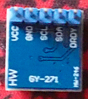
The GY-271 (Figure 1) is a 3-Axis Digital Compass sensor using IC number QMC5883L which is a magnetic and compass sensor. It operates up to 160Hz, connects via the I2C bus, has a 16-bit analog-to-digital conversion, uses 2.16 – 3.6VDC, consumes 75/100uA,150/250uA, 250/450uA and 450/850uA at 10Hz, 50Hz, 100Hz and 200Hz and can work at -40 to 80°C.
QMC5883L‘s registers
QMC5883L has registers for writing and reading the values as follows.
| Address | Description |
|---|---|
| 0x00 | lower byte of axis value X (LSB of X-Axis) |
| 0x01 | upper byte of axis value X (MSB of X-Axis) |
| 0x02 | lower byte of axis value Y (LSB of Y-Axis) |
| 0x03 | upper byte of axis value Y (MSB of Y-Axis) |
| 0x04 | lower byte of axis value Z (LSB of Z-Axis) |
| 0x05 | upper byte of axis value Z (MSB of Z-Axis) |
| 0x09 | control register 1 |
| 0x0A | control register 2 |
| 0x0B | Set/Reset Period Register |
Note
The QMC5883L documentation suggests setting the value of register position 0x0B to 0x01.
Control register 1
Control register 1 consists of 4 registers as follows:
| Bit No. | Register |
|---|---|
| 0..1 | Mode |
| 2..3 | ODR (Output Data Rate) |
| 4..5 | RNG (Fill scale) |
| 6..7 | OSR (Over Sample Ratio) |
where the values are as follows
| Setting | Base 2 |
|---|---|
| Mode_Standby | 0b00000000 |
| Mode_Continuous | 0b00000001 |
| ODR_10Hz | 0b00000000 |
| ODR_50Hz | 0b00000100 |
| ODR_100Hz | 0b00001000 |
| ODR_200Hz | 0b00001100 |
| RNG_2G | 0b00000000 |
| RNG_8G | 0b00010000 |
| OSR_512 | 0b00000000 |
| OSR_256 | 0b01000000 |
| OSR_128 | 0b10000000 |
| OSR_64 | 0b11000000 |
Control register 2
Contains the following registers.
| Bit No. | Register |
|---|---|
| 0 | INT_ENB |
| 6 | Rol_PNT |
| 7 | Soft_RS |
Connection
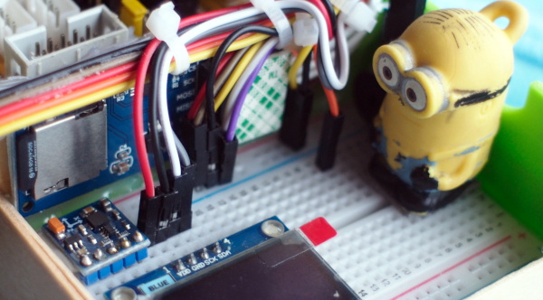
Connect via I2C bus as shown in Figure 3 and the sensor module has position value 0x0D by connecting to ESP8266 as follows.
| GY-271 | ESP8266 |
|---|---|
| Vcc | 3V3 |
| GND | GND |
| SDA | D2 |
| SCL | D1 |
Read the value
The reading is performed by reading from position 0x00 in order of low and high bytes of the X, Y, and Z axes:
buffer = i2c.readfrom_mem(QMC5883L_ADDR,RegXLo,6)
xLo = buffer[0]
xHi = buffer[1] <<8
yLo = buffer[2]
yHi = buffer[3] <<8
zLo = buffer[4]
zHi = buffer[5] <<8
x = xLo+xHi
y = yLo+yHi
z = zLo+zHi
Conversion
The conversion from the values of the X,Y and Z axes to the north direction is as follows.
heading = math.atan2(y, x)
heading = heading + declinationAngle
#Due to declination check for >360 degree
if(heading > 2*pi):
    heading = heading - 2*pi
#check for sign
if(heading < 0):
    heading = heading + 2*pi

#convert into angle
headingAngle = (heading * 180/pi)
Example Code
Converting the C++ code of e-Gizmo Mechatronix Central, C++ for Arduino, into Python for MicroPython is as follows:
###############################################################################
# GY-271/QMC5883L
# (C) 2021, JarutEx
# Ref: https://github.com/e-Gizmo/QMC5883L-GY-271-Compass-module
###############################################################################
import machine as mc
import sys
import math
from time import sleep #import sleep
pinSDA = mc.Pin(4)
pinSCL = mc.Pin(5)
QMC5883L_ADDR = 0x0D
i2c = mc.I2C(freq=2000000, scl=pinSCL, sda=pinSDA)
devices = i2c.scan()
if not (QMC5883L_ADDR in devices):
print("Not found GY-271 (QMC5883L)!")
sys.exit(1)
############## Register Location
RegCTRL1 = 0x09 # Control Register--> MSB(OSR:2,RNG:2,ODR:2,MODE:2)LSB
RegCTRL2 = 0x0A # Control Register2--> MSB(Soft_RS:1,Rol_PNT:1,none:5,INT_ENB:1)LSB
RegFBR = 0x0B # SET/RESET Period Register--> MSB(FBR:8)LSB
RegXLo = 0x00
RegXHi = 0x01
RegYLo = 0x02
RegYHi = 0x03
RegZLo = 0x04
RegZHi = 0x05
############## Cpntrol Register Value
Mode_Standby = 0b00000000
Mode_Continuous = 0b00000001
ODR_10Hz = 0b00000000
ODR_50Hz = 0b00000100
ODR_100Hz = 0b00001000
ODR_200Hz = 0b00001100
RNG_2G = 0b00000000
RNG_8G = 0b00010000
OSR_512 = 0b00000000
OSR_256 = 0b01000000
OSR_128 = 0b10000000
OSR_64 = 0b11000000
declinationAngle = 0.0404
pi = 3.14159265359
########### Init
ctrl1 = bytearray([Mode_Continuous|ODR_200Hz|RNG_8G|OSR_512])
i2c.writeto_mem(QMC5883L_ADDR,RegCTRL1, ctrl1)
i2c.writeto_mem(QMC5883L_ADDR,RegFBR, b'\x01')
########### Read
buffer = i2c.readfrom_mem(QMC5883L_ADDR,RegXLo,6)
xLo = buffer[0]
xHi = buffer[1] <<8
yLo = buffer[2]
yHi = buffer[3] <<8
zLo = buffer[4]
zHi = buffer[5] <<8
x = xLo+xHi
y = yLo+yHi
z = zLo+zHi
########### Convert
heading = math.atan2(y, x)
heading = heading + declinationAngle
#Due to declination check for >360 degree
if(heading > 2*pi):
heading = heading - 2*pi
#check for sign
if(heading < 0):
heading = heading + 2*pi
#convert into angle
headingAngle = (heading * 180/pi)
########### Show result
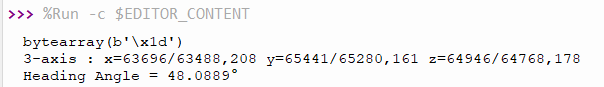
print("3-axis : x={}/{},{} y={}/{},{} z={}/{},{}".format(x,xHi,xLo,y,yHi,yLo,z,zHi,zLo))
print ("Heading Angle = {}°".format(headingAngle))
The result of running the sample code is as follows.
Conclusion
From this article, we found that Python programming has the advantage of being able to reuse code that is easier to reuse on boards that have a Python interpreter installed than it is to code in C/C++. We also found that the GY-271 module has two types of ICs, QMC5883L and HMC5883. Both of these ICs have different designs, the conversion methods are different, so the you must check the IC version on the module to make sure the code works properly. Finally, have fun with programming.
If you want to discuss or talk with us, feel free to leave comments below!
Reference
(C) 2020-2021, By Jarut Busarathid and Danai Jedsadathitikul
Updated 2021-10-06