This article discusses setting the GPIO and sending the digital status 0 or 1 to the port, starting with the LED on and off by connecting to the external LED circuit of the board as shown in Figure 1.

Project structure
The structure of the ESP-IDF project is as shown in Figure 2. In the project directory, there are files CMakeList.txt and sdkconfig with a directory named main to store the project source code. The directory contains the C language files and CMakeLists.txt.

From the structure in Figure 2, the file’s code of CMakeLists.txt must be generated as follows, in which the code content defines the minimum version of cmake program and configures the basic cmake implementation according to the original ESP-IDF and named the project as ep03.
cmake_minimum_required(VERSION 3.5)
include($ENV{IDF_PATH}/tools/cmake/project.cmake)
project(ep03)
What writes main/CMakeLists.txt is as follows to define a list of files to be compiled. This is defined as main.c and sets the directory where the header files are stored, meaning the same place as main.c or in the main directory.
idf_component_register(SRCS "main.c"
                    INCLUDE_DIRS "")
When creating a structure like Figure 2, select the target of the system to be ESP32 as follows:
idf.py set-target esp32
The sdkconfig is created by running the following command idf.py menuconfig.
idf.py menuconfig
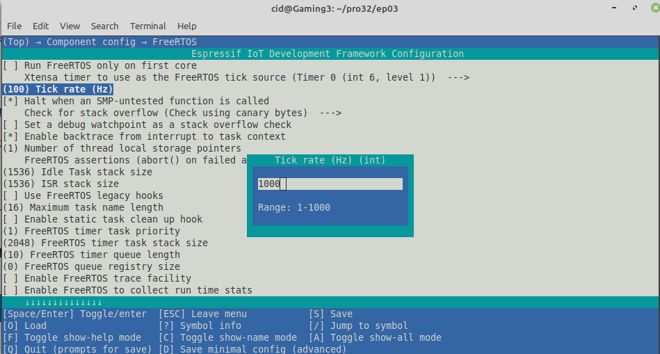
From the configuration screen, go to Component Config –> FreeRTOS and set the tick rate (Hz) to 1000 as shown in Figure 3, then save and exit the settings.
Commands
The GPIO implementation requires importing a header file named gpio.h located in the driver subfolder of the ESP-IDF, which can be imported with the include command:
#include <driver/gpio.h>
Pin selection must be specified with the following command.
gpio_pad_select_gpio( pin )
Commands for determining the functions of the pins have the following format: by the mode of the pins as GPIO_MODE_INPUT or GPIO_MODE_OUTPUT.
gpio_set_direction( pin, mode )
Assigning a digital voltage state to a pin has the following form of command:
gpio_set_level( pin, voltage )
For the delay, the delay instruction set must be run from FreeRTOS with the following delay command. By accessing the tick rate (Hz) value defined in the menuconfig procedure, it can be retrieved from a constant named portTICK_PERIOD_MS.
vTaskDelay( time )
If you want to use other GPIOs, you can read more articles as follows.
Example Code
The LED circuit used in this experiment is shown in Figures 4 and 5. The equipment used in the experiment are
- esp32
- Testing board
- LED
- Resister


From Figure 5, it can be seen that the pin GPIO13 is connected to the pin of the LED that is part of Vcc. This means that if the data is sent as 1, the LED will be on and if sent as 0 it will cause the LED to go out. As an example of the following program.
#include <stdio.h>
#include <time.h>
#include <string.h>
#include <math.h>
#include "driver/gpio.h"
#include "sdkconfig.h"
#include "freertos/FreeRTOS.h"
#include "freertos/task.h"

#define LED_PIN 13 // GPIO13

void app_main(void)
{
  printf("Ep.02 GPIO");
  gpio_pad_select_gpio(LED_PIN);
  gpio_set_direction(LED_PIN, GPIO_MODE_OUTPUT);

  while(1) {
    gpio_set_level(LED_PIN, 0);
    vTaskDelay( 500/portTICK_PERIOD_MS );
    gpio_set_level(LED_PIN, 1 );
    vTaskDelay( 500/portTICK_PERIOD_MS );
  }
}
Compile and upload
Compile it with the following command to get the result as shown in Figures 6 and 7.
idf.py build


The last step is to upload to the chip with the following command and will receive a report of the work as shown in Figures 8 and 9.
idf.py -p /dev/ttyUSB0 flash


From the example program, there is a working result at the LED as shown in Figures 10 and 11 alternately.


For an example of working with Board ESP32-C3 to make LED-RGB turn on alternately, change the program code as follows and will get the result as shown in Figure 12.
#include <stdio.h>
#include <time.h>
#include <string.h>
#include <math.h>
#include "driver/gpio.h"
#include "sdkconfig.h"
#include "freertos/FreeRTOS.h"
#include "freertos/task.h"

#define LED_R_PIN 3
#define LED_G_PIN 4
#define LED_B_PIN 5

void app_main(void)
{
  printf("C3 LEDs");
  gpio_pad_select_gpio(LED_R_PIN);
  gpio_set_direction(LED_R_PIN, GPIO_MODE_OUTPUT);
  gpio_pad_select_gpio(LED_G_PIN);
  gpio_set_direction(LED_G_PIN, GPIO_MODE_OUTPUT);
  gpio_pad_select_gpio(LED_B_PIN);
  gpio_set_direction(LED_B_PIN, GPIO_MODE_OUTPUT);

  while(1) {
    gpio_set_level(LED_R_PIN, 1);
    vTaskDelay( 500/portTICK_PERIOD_MS );
    gpio_set_level(LED_R_PIN, 0 );
    vTaskDelay( 500/portTICK_PERIOD_MS );
    gpio_set_level(LED_G_PIN, 1);
    vTaskDelay( 500/portTICK_PERIOD_MS );
    gpio_set_level(LED_G_PIN, 0 );
    vTaskDelay( 500/portTICK_PERIOD_MS );
    gpio_set_level(LED_B_PIN, 1);
    vTaskDelay( 500/portTICK_PERIOD_MS );
    gpio_set_level(LED_B_PIN, 0 );
    vTaskDelay( 500/portTICK_PERIOD_MS );
    gpio_set_level(LED_R_PIN, 1 );
    gpio_set_level(LED_G_PIN, 1 );
    gpio_set_level(LED_B_PIN, 0 );
    vTaskDelay( 500/portTICK_PERIOD_MS );
    gpio_set_level(LED_R_PIN, 0 );
    gpio_set_level(LED_G_PIN, 1 );
    gpio_set_level(LED_B_PIN, 1 );
    vTaskDelay( 500/portTICK_PERIOD_MS );
    gpio_set_level(LED_R_PIN, 1 );
    gpio_set_level(LED_G_PIN, 0 );
    gpio_set_level(LED_B_PIN, 1 );
    vTaskDelay( 500/portTICK_PERIOD_MS );
    gpio_set_level(LED_R_PIN, 1 );
    gpio_set_level(LED_G_PIN, 1 );
    gpio_set_level(LED_B_PIN, 1 );
    vTaskDelay( 500/portTICK_PERIOD_MS );
    gpio_set_level(LED_R_PIN, 0 );
    gpio_set_level(LED_G_PIN, 0 );
    gpio_set_level(LED_B_PIN, 0 );
    vTaskDelay( 500/portTICK_PERIOD_MS );
  }
}
It is important not to forget that the target must be changed to esp32c3 with the following command before uploading the program.
idf.py set-target esp32c3

Conclusion
From this article, you will find that programming with ESP-IDF is quite complicated since the tool is in character mode(But considered convenient for developers who use Linux operating systems), but if considering the programming process, it will be convenient because it can be written, defined and executed like writing with Arduino, but the instructions are different.
The microcontroller’s configuration or settings must first be made to idf.py menuconfig to set the frequency or other so that it works properly as needed. Before entering the menuconfig, you must set the target correctly, which are esp32 esp32s2 esp32c3 and esp32s3 in this article is esp32.
Finally, have fun with programming.
If you want to talk with us, feel free to leave comments below!!
(C) 2020-2021, By Jarut Busarathid and Danai Jedsadathitikul
Updated 2021-12-17