This article describes the use of the GPIO of ESP32 to output analog signal through 8-bit DAC module of ESP32 microcontroller by creating a zig graph (Figure 7) to the speaker module as shown in Figure 1.

Project structure
The structure of the ESP-IDF project is as shown in Figure 2. In the project directory or folder there are files CMakeList.txt and sdkconfig with a directory named main to store the project source code. The directory contains the C language files and CMakeLists.txt.
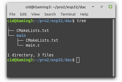
From the structure in Figure 2, the CMakeLists.tx file’s code must be generated as follows, in which the code content defines the minimum version of cmake and configures the default cmake implementation according to the original ESP-IDF and named the project as ep07.
cmake_minimum_required(VERSION 3.5)
include($ENV{IDF_PATH}/tools/cmake/project.cmake)
project(ep07)
What writes main/CMakeLists.txt is as follows to define a list of files to be compiled. This is defined as main.c and sets the directory where the header files are stored, meaning the same place as main.c or in the main directory.
idf_component_register(SRCS "main.c"
                    INCLUDE_DIRS "")
When creating a structure like Figure 2, select the target of the system to be ESP32 as follows:
idf.py set-target esp32
The sdkconfig is created by running the following command idf.py menuconfig.
idf.py menuconfig
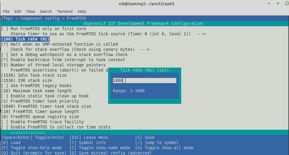
From the configuration screen, go to Component Config –> FreeRTOS and set the tick rate (Hz) to 1000 as shown in Figure 3, then save and exit the settings.
DAC usage
The ESP32 microcontroller has a digital-to-analog converter circuit to output to an external circuit or a DAC (Digital to Analog) with 8-bit resolution and supports DMA (Direct Memory Access) via the I2S bus with an external module (And will be discussed in the next article). It makes it possible to adjust the voltage at the DAC pin to 0 to 3V3 by sending values from 0 to 255 to that pin. The ESP32 provides 2 DAC circuits:
- DAC1 via pin 25
- DAC2 via pin 26
To use the DAC, the header file must be imported as follows: to enable or disable I2S.
#include <driver/dac.h>
and execute the dac_common.h header file for the ESP32 microcontroller’s DAC instructions.
#include <driver/dac_common.h>
Commands
To enable or disable the I2S bus for DMA access to the external DAC converter module, use the dac_i2s_enable() and dac_i2s_disable() commands as follows.
esp_err_t dac_i2s_enable()
esp_err_t dac_i2s_disable()
Returning values from the execution of the command dac_i2s_enable and dac_i2s_disable are as follows.
- ESP_OK
The commands for enabling and disabling the DAC in the specified channel have the following syntax.
dac_output_enable( export )
dac_output_disable( export )
The output channel values are as follows.
- DAC_CHANNEL_1 for pin 25
- DAC_CHANNEL_2 for pin 26
For analog outputs, data must be sent as values in the range 0 to 255 to represent the voltage in the range 0 to 3V3 with the dac_output_voltage() command as follows.
dac_output_voltage( ch, value )
If you want to use other GPIOs, you can read more articles as follows.
Example Code
The LED circuit used in this experiment is shown in Figure 5. The equipment used in the experiment are:
- esp32
- Experiment board
- Speaker module
- transister
- 2 resister
- buzzer

An example program to pass values 0 through 255 to pin 25 and when the increment is greater than 255, change the value to 0 and the following loop is coded:
#include <stdio.h>
#include <time.h>
#include <string.h>
#include <math.h>
#include <sdkconfig.h>
#include <driver/gpio.h>
#include <driver/dac.h>
#include <driver/dac_common.h>
#include <freertos/FreeRTOS.h>
#include <freertos/task.h>

#define pinDAC DAC_CHANNEL_2

void wave1() {
  int dValue=0;
  printf("Start wave1 ...");
  dac_output_enable( pinDAC );
  while (true) {
    dac_output_voltage( pinDAC, dValue++ );
    vTaskDelay( 10/portTICK_PERIOD_MS );
    if (dValue > 255) {
        break;
    }
  }
  dac_output_disable( pinDAC );
  printf("done.\n");
}

void app_main(void)
{
  printf("Ep.07 DAC\n");
  dac_i2s_enable();
  dac_i2s_disable();

  while(1) {
    wave1();
    vTaskDelay( 10/portTICK_PERIOD_MS );
  }
}
Compile and upload
Compile, then flash it into the chip and run the Serial Monitor program as follows:
idf.py -p /dev/ttyUSB0 build flash monitor
An example program output is shown in Figure 6, and the graph displayed with an oscilloscope is shown in Figure 7.


Conclusion
From this article you will find that There are 3 steps for importing analog signals:
- Enable DAC1 or DAC2 with the dac_output_enable() command.
- Export data with command dac_output_voltage()
- Disable DAC1 or DAC2 with dac_output_disable()
However, this article skips the I2S implementation (we don’t have an I2S module at the time of writing) and the cosine waveform generation instruction set that the library provides which will be written in the next article. Finally, have fun with programming.
If you want to talk with us, feel free to leave comments below!!
Reference
- ESP-IDF : DAC
(C) 2020-2021, By Jarut Busarathid and Danai Jedsadathitikul
Updated 2021-12-29