This article discusses the use of the ESP32’s GPIO as an analog signal output through the 8-bit DAC module of the ESP32 microcontroller. In this article, we use Cosine wave generation to output the analog signal of the microcontroller through the speaker and show the waveform obtained from the oscilloscope display. The experimental board is still used as shown in Figure 1.

Project structure
The structure of the ESP-IDF project is as shown in Figure 2. In the project directory, there are files CMakeList.txt and sdkconfig with a directory named main to store the project source code. The directory contains the C language files and CMakeLists.txt.

From the structure in Figure 2, the CMakeLists.txt file’s code must be generated as follows, where the content in the code defines the minimum version of cmake and configures the default cmake implementation according to the original ESP-IDF and named the project as ep08.
cmake_minimum_required(VERSION 3.5)
include($ENV{IDF_PATH}/tools/cmake/project.cmake)
project(ep08)
What writes main/CMakeLists.txt is as follows to define a list of files to be compiled. This is defined as main.c and sets the directory where the header files are stored, meaning the same place as main.c or in the main directory.
idf_component_register(SRCS "main.c"
                    INCLUDE_DIRS "")
When creating a structure like Figure 2, select the target of the system to be ESP32 as follows:
idf.py set-target esp32
The sdkconfig is created by running the following command idf.py menuconfig.
idf.py menuconfig
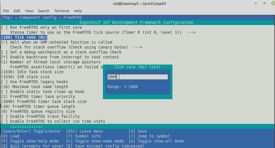
From the configuration screen, go to Component Config –> FreeRTOS and set the tick rate (Hz) to 1000 as shown in Figure 3 , then save and exit the settings.
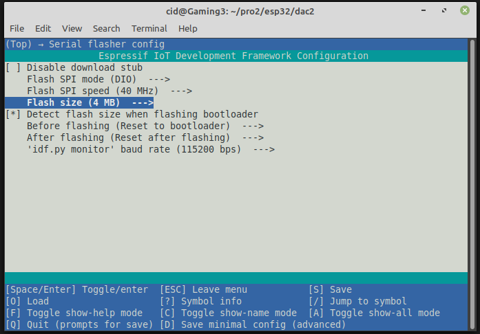
What is often forgotten is to set the capacity of the ROM memory (Flash size) as shown in Figure 4 to match the size installed on the board from the Serial flasher config, which in the article is 4MB. After that, press S and Q to save and exit the settings.
Using a cosine waveform
The ESP32 microcontroller DAC library contains a set of instructions for enabling/disabling cosine waveforms on channels 1 and 2 by specifying the wave characteristics in a data structure of type dac_cw_config_t. The details are as follows.
struct dac_cw_config_t {
dac_channel_t en_ch;
dac_cw_scale_t scale;
dac_cw_phase_t phase;
uint32_t freq;
uint8_t offset;
};
Each feature is as follows.
- en_ch is the channel number that enables cosine wave generation. The channels are
- DAC_CHANNEL_1 is pin 25 of ESP32 and pin 17 of ESP32-S2
- DAC_CHANNEL_2 is pin 26 of ESP32 and pin 18 of ESP32-S2
- scale is the amplitude of the wave, which can be set in 4 levels:
- DAC_CW_SCALE_1 normal height wave
- DAC_CW_SCALE_2 ½ height wave
- DAC_CW_SCALE_4 ¼ height wave
- DAC_CW_SCALE_8 1/8 height wave
- phase is the phase shift value of the wave which can be defined in two ways:
- DAC_CW_PHASE_0 start from 0 degree
- DAC_CW_PHASE_180 start from 180 degrees
- freq is the frequency of the wave, which is in the range of 130Hz ~ 55,000Hz, the highest value that can be set is 100KHz, but the high-frequency spectrum is the range that the human ear can’t hear.
- offset for determining the level of DC voltage brought out in the form of a cosine wave which must be configured in the range -128 ~127, the thing that must be careful is entering unreasonable values will affect the wave height range.
To use the DAC, the header file must be imported as follows: to enable or disable I2S.
#include <driver/dac.h>
and executing the dac_common.h header file for the ESP32 microcontroller’s DAC instructions.
#include <driver/dac_common.h>
For the tunnel values are defined in a header file named dac_channel.h
Commnads
The cosine wave generation can be turned on or off by running the command dac_cw_generator_enable() and dac_cw_generator_disable() as follows.
esp_err_t dac_cw_generator_enable()
esp_err_t dac_cw_generator_disable()
The returning value from the execution of the command dac_cw_generator_enable and dac_cw_generator_disable are as follows:
- ESP_OK
And the command for setting the operation of cosine wave generation has the following form:
esp_err_t dac_cw_generator_config( &ตัวแปรที่เก็บการตั้งค่า )
The returning value from the execution of the command dac_cw_generator_enable and dac_cw_generator_disable are as follows:
- ESP_OK if success
- ESP_ERR_INVALID_ARG if error
If you want to use other GPIOs, you can read more articles as follows.
Example Code
The LED circuit used in this experiment is shown in Figure 5. The devices used in the experiment are:
- esp32
- Experiment board
- speaker module
- transister
- 2 resisters
- buzzer

Here’s an example program that generates 262Hz, which is a piano’s C-sound frequency for 2 seconds. Write the code as follows:
#include <stdio.h>
#include <time.h>
#include <string.h>
#include <math.h>
#include <sdkconfig.h>
#include <driver/gpio.h>
#include <driver/dac.h>
#include <driver/dac_common.h>
#include <freertos/FreeRTOS.h>
#include <freertos/task.h>

#define pinDAC DAC_CHANNEL_2

void app_main(void)
{
  dac_cw_config_t cwCfg;

  cwCfg.en_ch = pinDAC;
  cwCfg.scale = DAC_CW_SCALE_1;
  cwCfg.phase = DAC_CW_PHASE_180;
  cwCfg.freq = 262; // 262Hz
  cwCfg.offset = 127;

  printf("Ep.08 DAC\n");
  dac_i2s_enable();
  dac_i2s_disable();
  if (dac_cw_generator_config(&cwCfg) == ESP_OK) {
    printf("Start cosine-wave generator ...");
    dac_cw_generator_enable();
    dac_output_enable( pinDAC );
    vTaskDelay( 2000/portTICK_PERIOD_MS ); // 2 seconds
    dac_cw_generator_disable();
    dac_output_disable( pinDAC );
    printf("done.\n");
  } else {
    printf("Error : ESP_ERR_INVALID_ARG!\n");
  }
  while (1) {
    vTaskDelay( 10/portTICK_PERIOD_MS );
  }
}
In the case of creating other audio frequencies, the frequency values can be changed as follows (source ammmusic)
- do, 262Hz
- re, 294Hz
- mi, 330Hz
- fa, 349Hz
- so, 370Hz
- la, 440Hz
- ti 495Hz
Compile and upload
Compile, then flash it into the chip and run the Serial Monitor program as follows:
idf.py -p /dev/ttyUSB0 build flash monitor
An example of the result is shown in Figure 6, and the graph displayed with an oscilloscope is shown in Figure 7.


From Figure 7, it can be seen that the top of the wave is incomplete. So try changing the new settings as follows and the result of the wave is as shown in Figure 8.
  cwCfg.en_ch = pinDAC;
  cwCfg.scale = DAC_CW_SCALE_2;
  cwCfg.phase = DAC_CW_PHASE_0;
  cwCfg.freq = 262; // 262Hz
  cwCfg.offset = 48;
Conclusion
From this article you will find that Analog signal output is a three-step process:
- Configured with dac_cw_generator_config()
- Start with dac_cw_generator_enable()
- Stop with dac_cw_generator_disable()
However, the nature of the waveform affects the sound quality, therefore, always check the settings and the resulting waveform to avoid inaccuracies as shown in Figure 7. Finally, have fun with the programming.
If you want to walk with us, feel free to leave comments below!!!
References
(C) 2020-2021, By Jarut Busarathid and Danai Jedsadathitikul
Updated 2021-12-30