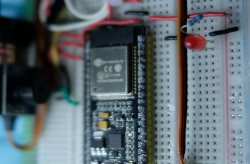
This article discusses the use of the ESP32’s GPIO to output digital signals such as PWM or Pulse Width Modulation or LEDC (LED Control), which enables frequency generation or adjusts the proportion of 1 and 0 states in 1 waveform. Thus, in the absence of the DAC, we can still adjust the average voltage at that pin as needed and it can be applied to control servo motors as well. Therefore, in this article, we will learn how to use PWM and apply it to frequency transmission instead of DAC (from the previous article) and LED dimming using the experimental board as shown in Figure 1.
Project structure
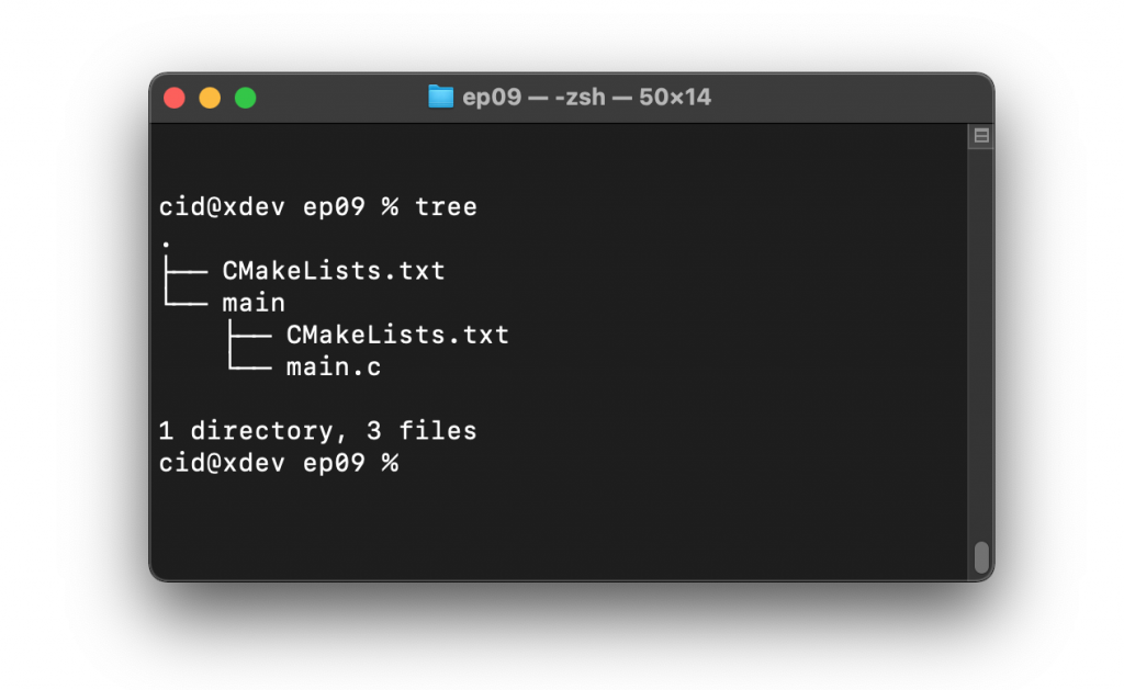
The structure of the ESP-IDF project is as shown in Figure 2. In the project directory, there are files CMakeList.txt and sdkconfig with a directory named main to store the project source code. The directory contains the C language files and CMakeLists.txt.
From the structure in Figure 2, the CMakeLists.txt file’s code must be generated as follows, in which the code content defines the minimum version of cmake program and configures the default cmake implementation according to the original ESP-IDF and names the project as ep09.
cmake_minimum_required(VERSION 3.5)
include($ENV{IDF_PATH}/tools/cmake/project.cmake)
project(ep09)
What is written in the file main/CMakeLists.txt is as follows to define a list of files to be compiled. This is defined as main.c and sets the directory where the header files are stored, meaning the same place as main.c or in the main directory.
idf_component_register(SRCS "main.c"
                    INCLUDE_DIRS "")
When creating a structure like Figure 2, select the target of the system to be ESP32 as follows:
idf.py set-target esp32
The sdkconfig is created by running the following command idf.py menuconfig.
idf.py menuconfig
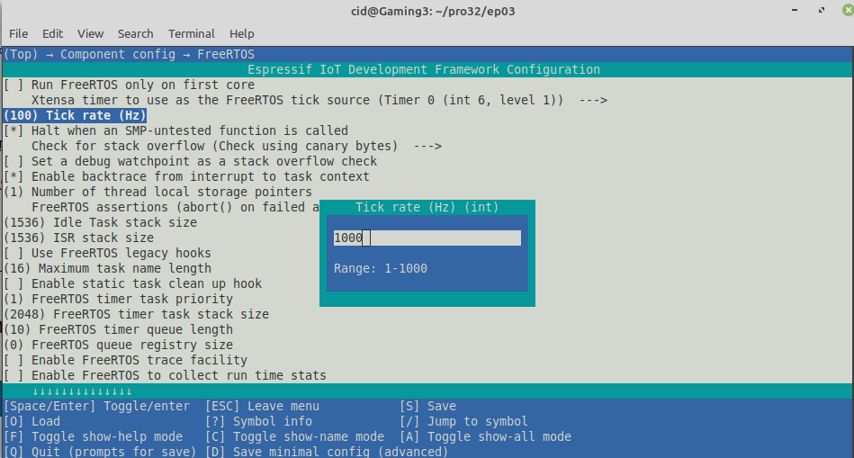
From the configuration screen, go to Component Config –> FreeRTOS and set the tick rate (Hz) to 1000 as shown in Figure 3, then save and exit the settings.
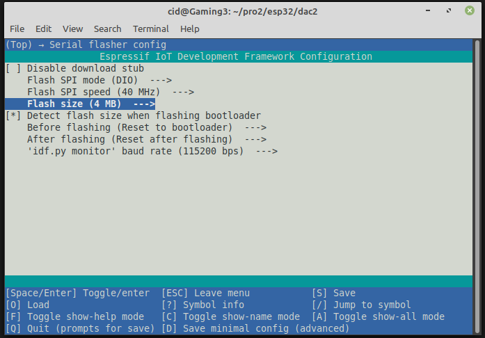
What is often forgotten is to set the capacity of the ROM memory (Flash size) as shown in Figure 4 to match the size installed on the board from the Serial flasher config, which in the article is 4MB. After that, press S and Q to save and exit the settings.
LEDC
espressif uses the LEDC class as the main LED intensity control module. This module uses PWM as a voltage driver connected to the LED and can be used for 16 channels that can generate waves independently of each other, divided into 2 types, as shown in Figure 5:
- High Speed Channel
- Low Speed Channel
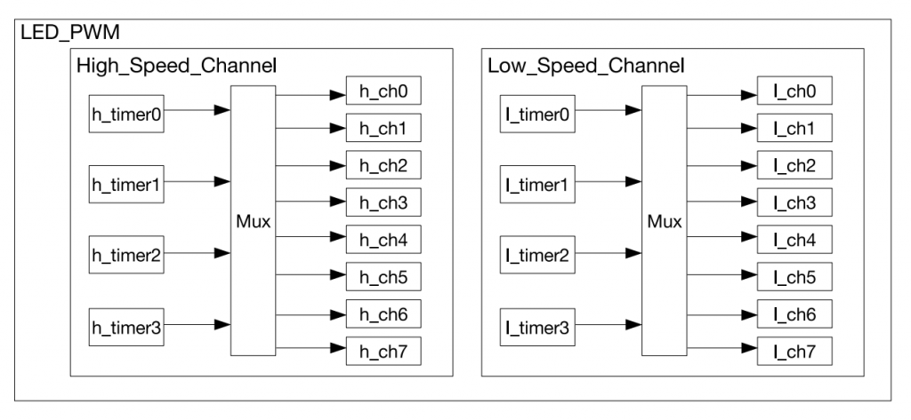
From Figure 14-1 LED_PWM Architecture
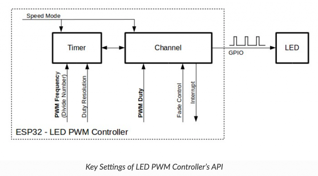
The use of PWM or LEDC consists of 3 steps as follows (Figure 6)
- Set the timer.
- Set up a channel.
- Change the signal of the PWM
From https://docs.espressif.com/projects/esp-idf/en/latest/esp32/api-reference/peripherals/ledc.html
Timer setting
It is a configuration that defines a type of data structure. ledc_timer_config_t which has a list of members in the structure as follows
struct ledc_timer_config_t {
ledc_mode_t speed_mode;
ledc_timer_bit_t duty_resolution;
ledc_timer_bit_t bit_num;
ledc_timer_t timer_num;
uint32_t freq_hz;
ledc_clk_cfg_t clk_cfg;
};
From the members within the structure, speed_mode is a mode of operation based on the following options.
- LEDC_HIGH_SPEED_MODE
- LEDC_LOW_SPEED_MODE
- LEDC_SPEED_MODE_MAX
The value of duty_resolution sets the resolution of the duty value, bit_num has been deprecated since ESP-IDF version 2.x, but it’s maintained for compatibility only, so it’s 0.
timer_num is the number of the timer to use which can be set to 0-3
- LEDC_TIMER_0
- LEDC_TIMER_1
- LEDC_TIMER_2
- LEDC_TIMER_3
The value freq_hz is the frequency to be generated and the value of clk_cfg is the source.
- LEDC_AUTO_CLK
- LEDC_USE_REF_TICK use the clock source from REF_TICK.
- LEDC_USE_ABP_TICK use the clock source from ABP.
- LEDC_USE_RTC8M_CLK use the clock source from RTC8M
The command of setting the timer is as follows.
esp_err_t ledc_timer_config( const ledc_timer_config_t * timer_conf)
The return value from the command is as follows.
- ESP_OK success
- ESP_ERR_INVALID_ARG Invalid
- ESP_FAIL an error occurred due to the pre-divider settings used to calculate the frequency and about the value of duty_resolution.
Channel Settings
Step 2 Configure the channel used to drive the signal to the external circuit using the ledc_channel_config() command in the following format.
esp_err_t ledc_channel_config( const ledc_channel_config_t * ledc_conf )
จากรูปแบบของคำสั่งจะพบว่าอาร์กิวเมนต์หรือพารามิเตอร์ที่ต้องส่งให้กับคำสั่งนั้นเป็นข้อมูลในแบบ ledc_channel_config_t ซึ่งมีโครงสร้างดังนี้
struct ledc_channel_config_t {
int gpio_num;
ledc_mode_t speed_mode;
ledc_channel_t channel;
ledc_intr_type_t intr_type;
ledc_timer_t timer_sel;
uint32_t duty;
int hpoint;
unsigned int output_invert;
struct ledc_channel_config::[anonymous]flags;
};
From the structure, the details are as follows.
- gpio_num is the PIN used for signal output.
- speed_mode
- LEDC_HIGH_SPEED_MODE
- LEDC_LOW_SPEED_MODE
- channel
- LEDC_CHANNEL_0
- LEDC_CHANNEL_1
- LEDC_CHANNEL_2
- LEDC_CHANNEL_3
- LEDC_CHANNEL_4
- LEDC_CHANNEL_5
- LEDC_CHANNEL_6
- LEDC_CHANNEL_7
- LEDC_CHANNEL_MAX
- intr_type interupt on / off
- LEDC_INTR_DISABLE
- LEDC_INTR_FADE_END
- timer_sel clock source
- LEDC_TIMER_0
- LEDC_TIMER_1
- LEDC_TIMER_2
- LEDC_TIMER_3
- duty in range [0, 2duty_resolution)
- hpoint , max = 0xfffff
- output_invert
- 0 no invert
- 1 invert
- flags led status
The value returned from function are
- ESP_OK
- ESP_ERR_INVALID_ARG
PWM convertion
At this stage, the specified channel and the PWM signal are started to be generated based on the specified duty and freq values. The PWM value changes can be made with two groups of commands based on the type of mode selection.
Changing when using software mode
To read the duty value, use the command ledc_get_duty() in the following format
duty=ledc_get_duty( ledc_mode_t speed_mode, ledc_channel_t channel)
The new duty setting can be performed with the following command.
esp_err_t ledc_set_duty( ledc_mode_t speed_mode, ledc_channel_t channel, duty)
and commands for modifying the value of a duty defined in ledc_set_duty() has the following format.
esp_err_t ledc_update_duty( ledc_mode_t speed_mode,ledc_channel_t channel)
Changing when using hardware mode
The hardware mode works differently than the software one, in that it can fade from one duty value to another. If you want to enable it, you have to run the command ledc_fade_function_install() as the following format
esp_err_t ledc_fade_func_install( int intr_alloc_flags )
When deactivating the hardware mode operation, the command must be called as follows:
ledc_fade_func_uninstall()
Working with duty values is based on the principle of gradually shifting from one value to another. Here are the relevant commands for setting fading:
- ledc_fade_start( ledc_mode_t speed_mode, ledc_channel_t chennel, ledc_fade_mode_t fade_mode ) for starting
- ledc_set_fade_with_time( ledc_mode_t speed_mode, ledc_channel_t channel, uint32_t target_duty, int max_fade_time_ms) To set the amount of time it takes to change a duty value from the current value to target_duty in max_fade_time_ms in milliseconds.
- ledc_set_fade_with_step( ledc_mode_t speed_mode, ledc_channel_t channel, uint32_t target_duty, uint32_t scale, uint32_t cycle_num) Required to fade by defining the number of fade steps cycle_num times, each time changing scale.
- ledc_set_fade( ledc_mode_t speed_mode, ledc_channel_t channel, uint32_t duty, ledc_duty_direction_t fade_direction, uint32_t step_num, uint32_t duty_cycle_num, uint32_t duty_scale)
ledc_fade_mode_t values are
- LEDC_FADE_NO_WAIT change immediately
- LEDC_FADE_WAIT_DONE gradually change the value to the new duty value.
ledc_duty_direction_t values are
- LEDC_DUTY_DIR_DECREASE gradually decrease
- LEDC_DUTY_DIR_INCREASE gradually increase
Pin assignments and downtime
To determine the output pins, use the following commands:
esp_err_t ledc_set_pin(int gpio_num, ledc_mode_t speed_mode, ledc_channel_t ledc_channel )
You can turn off the clock generation by calling the ledc_stop() command as shown below.
esp_err_t ledc_stop(ledc_mode_t speed_mode, ledc_channel_t channel, uint32_t idle_level)
where idle_level is the digital signal level after the PWM has been stopped.
To use PWM or LEDC, the header file must be imported as follows: to be used to enable or disable the following functions:
#include <driver/ledc.h>
If you want to use other GPIOs, you can read more articles as follows.
Example Code
An example program that esp-idf provides has 2 characters:
Equipment
The equipment used in the experiment included
- esp32
- Experiment board
- LED and resister
- Speaker module
- Transister
- 2 resisters
- buzzer
Code
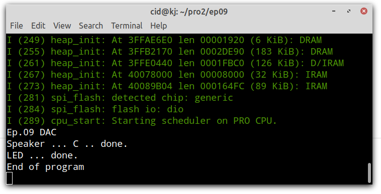
An example program generates 262Hz, which is the frequency of the piano’s C (“do”) tone for 2 seconds, after which the LEDs are lighted and dimmed from the darkest to the brightest and from brightest to darkest. The whole code can be written as follows:
#include <stdio.h>
#include <time.h>
#include <string.h>
#include <math.h>
#include <sdkconfig.h>
#include <driver/gpio.h>
#include <driver/ledc.h>
#include <freertos/FreeRTOS.h>
#include <freertos/task.h>

#define pinSpk 26
#define pinLED 23

#define LEDC_DUTY_MAX   (8191)
#define LEDC_DUTY       (4095) // change duty to 50% from (213-1)*50/100 so it's 4095

void testSpk() {
  // Speaker
  printf("Speaker ... C .. ");
  ledc_timer_config_t ledc_timer = {
        .speed_mode       = LEDC_LOW_SPEED_MODE,
        .timer_num        = LEDC_TIMER_0,
        .duty_resolution  = LEDC_TIMER_13_BIT, // 213
        .freq_hz          = 262,
        .clk_cfg          = LEDC_AUTO_CLK
  };
  ledc_timer_config(&ledc_timer);

  ledc_channel_config_t ledc_channel = {
        .speed_mode     = LEDC_LOW_SPEED_MODE,
        .channel        = LEDC_CHANNEL_0,
        .timer_sel      = LEDC_TIMER_0,
        .intr_type      = LEDC_INTR_DISABLE,
        .gpio_num       = pinSpk,
        .duty           = 0, // Set duty to 0%
        .hpoint         = 0
  };
  ledc_channel_config(&ledc_channel);

  // สร้างความถี่ 262Hz
  ledc_set_duty(LEDC_LOW_SPEED_MODE, LEDC_CHANNEL_0, 262);
  ledc_update_duty(LEDC_LOW_SPEED_MODE, LEDC_CHANNEL_0);

 // delay 2 sec
  vTaskDelay( 2000/portTICK_PERIOD_MS );

  printf("done.\n");

  // turn off LEDC or PWM
  ledc_stop(LEDC_LOW_SPEED_MODE, LEDC_CHANNEL_0, 0);
}

void testLED() {
  // fade the LED
  printf("LED ... ");
  ledc_timer_config_t ledc_timer = {
        .speed_mode       = LEDC_LOW_SPEED_MODE,
        .timer_num        = LEDC_TIMER_1,
        .duty_resolution  = LEDC_TIMER_13_BIT,
        .freq_hz          = 50,  // Set output frequency at 5 kHz
        .clk_cfg          = LEDC_AUTO_CLK
  };
  ledc_timer_config(&ledc_timer);
  ledc_channel_config_t ledc_channel = {
        .speed_mode     = LEDC_LOW_SPEED_MODE,
        .channel        = LEDC_CHANNEL_1,
        .timer_sel      = LEDC_TIMER_1,
        .intr_type      = LEDC_INTR_DISABLE,
        .gpio_num       = pinLED,
        .duty           = 0, // Set duty to 100%
        .hpoint         = 0
  };
  ledc_channel_config(&ledc_channel);

  int i;
  // change duty to light up the led
  for (i=200; i>0; i--) {
    ledc_set_duty(LEDC_LOW_SPEED_MODE, LEDC_CHANNEL_1,i*40);
    ledc_update_duty(LEDC_LOW_SPEED_MODE, LEDC_CHANNEL_1);
    // delay
    vTaskDelay( 50/portTICK_PERIOD_MS );
  }

  // change duty value to turn off led
  for (i=0; i<200; i++) {
    ledc_set_duty(LEDC_LOW_SPEED_MODE, LEDC_CHANNEL_1,i*40);
    ledc_update_duty(LEDC_LOW_SPEED_MODE, LEDC_CHANNEL_1);
    // delay
    vTaskDelay( 50/portTICK_PERIOD_MS );
  }

  printf("done.\n");

  // turn off LEDC or PWM
  ledc_stop(LEDC_LOW_SPEED_MODE, LEDC_CHANNEL_1, 1);
}

void app_main(void)
{
  printf("Ep.09 DAC\n");
  testSpk();
  testLED();
  printf("End of program\n");
}
Compile and upload
Compile, then flash it into the chip and run the Serial Monitor program as follows:
idf.py -p /dev/ttyUSB0 build flash monitor
Conclusion
From this article, you will find that the use of PWM or LEDC consists of 3 steps:
- set timer with ledc_timer_config()
- set channel with ledc_channel_config()
- control with ledc_set_duty(), ledc_update_duty() and ledc_stop()
However, the example this time is specifically about using the hardware-free PWM part of the timer to fade. But in the example, the LEDs are faded by programming to cycle. However, when we have written an article to interrupt and already use the timer, we will come back to do this example again. And finally, have fun with programming.
If you want to talk with us, feel free to leave comments below!!
References
- WiKiPedia : Pulse-width modulation
- ESP-IDF : LEDC
(C) 2020-2021, By Jarut Busarathid and Danai Jedsadathitikul
Updated 2021-12-31