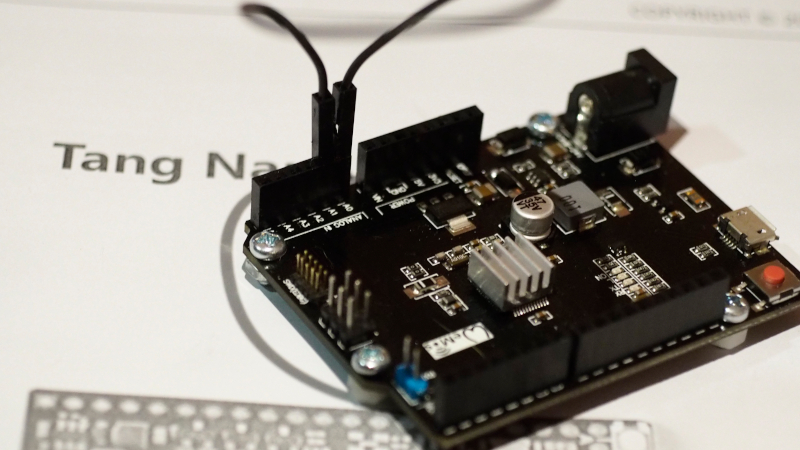
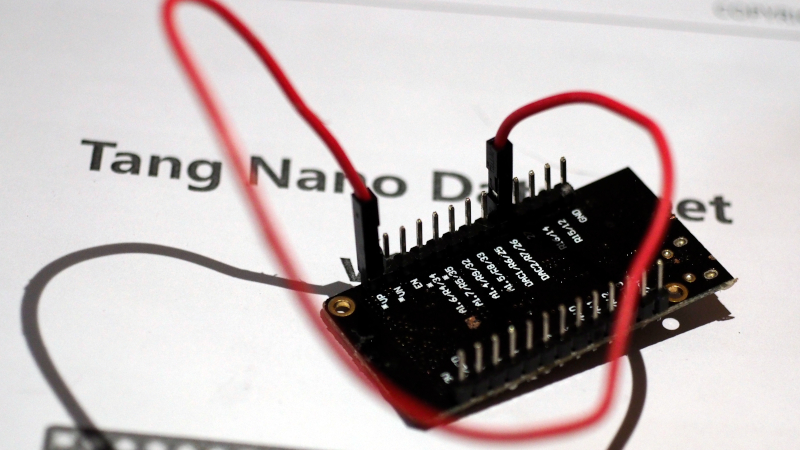
This article introduces the ESP32 and SAM-D21 microcontroller board to learn how to use ADC (Analog to Digital Converter) and DAC (Digital to Analog Converter) instruction by connecting the DAC pin to ADC as shown in Figures 1 (Connect A0 to A1 of Board SAM-D21 ) and 2 (Connect Pin GPIO26 to GPIO36 of ESP32) to send data to DAC and have ADC read it back. Then send the results out to the serial port for display with the Serial Plotter, which is an example program to send 3 types of data, which is a zigzag graph, triangular graph and waveform graph from the sinusoidal function
Instructions
The instructions for using the ADC and DAC are as follows.
ADC Resolution Adjustment
The instructions for adjusting the ADC resolution of both the ESP32 and the SAM-D21 are implemented as follows, where x is the number of bits in operation.
analogReadResolution( x )
Commands for adjusting the resolution of the DAC.
The DAC resolution command for the SAM-D21 uses the following format, where x is the integer value of the bit value to be used. Usually has a value of 10.
analogWriteResolution(x)
Commands for reading ADC values
The command format for reading ADC values of the SAM-D21 and ESP32 uses the analogRead( ) command and specifies the PIN to read pins 32,33,34,35,36 and 39, the SAM-D21 uses A1 pin.
data = analogRead( pin )
DAC output data command
For the SAM-D21’s 10-bit data output instructions, the following format can be used with pin A0.
analogWrite( pin, output )
For esp32, run the command dacWrite() specifying pin 25 or 26 as follows:
dacWrite( pin, output )
Example Code
An example of a program to draw 3 types of graphs are a zigzag (refer to the examples of Figures 3 and 4), a triangular graph (Figure 5 and 6), and a sine wave curve (Figure 7 and 8). The code is as follows.
Zigzag graph
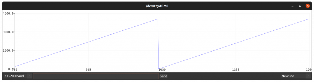
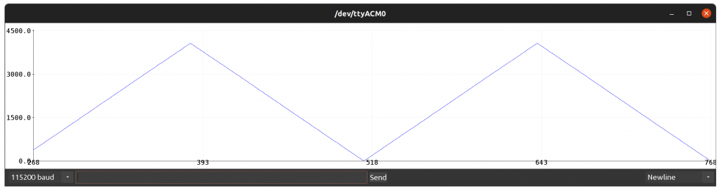
The zigzag graph is passed 0 to the maximum possible value of the DAC sector, after which it loops through again. The code for SAM-D21 is as follows, and the result is as shown in Figure 3.
#include <Arduino.h>

#define pinSpk A0
#define pinMic A1
int adcValue;

void setup() {
  SerialUSB.begin(115200);
  analogReadResolution(12);
  analogWriteResolution(10);

}

void loop() {
  for (int i = 0; i < 1024; i += 4) {
    analogWrite( pinSpk, i);
    adcValue = analogRead(pinMic);
    SerialUSB.println(adcValue);
  }
}
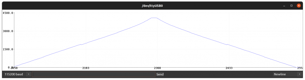
The programming code for the esp32 is as follows. Be careful of the maximum value passed to the DAC, as the ESP32 has an 8-bit resolution DAC, capable of transmitting values in the range 0 to 255.
#include <Arduino.h>

#define pinSpk 26
#define pinMic 36
int adcValue;

void setup() {
  Serial.begin(115200);
  analogReadResolution(12);
}

void loop() {
  for (int i = 0; i < 255; i++) {
    dacWrite( pinSpk, i );
    adcValue = analogRead(pinMic);
    Serial.println(adcValue);
  }
}
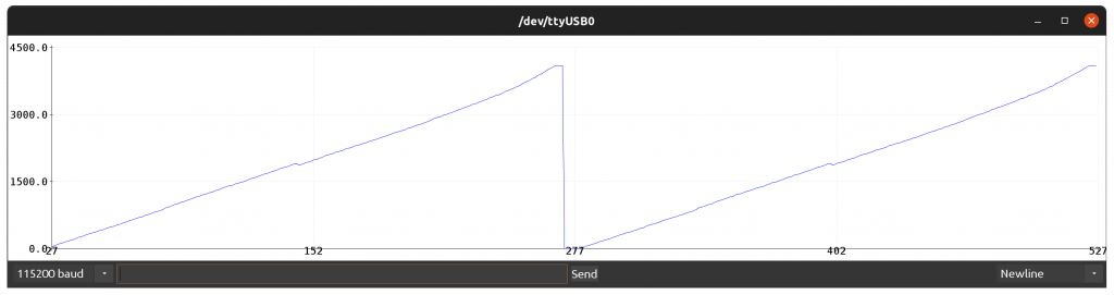
From Figure 4, the ADC graph of the ESP32 is non-linear compared to Figure 3. From our experience, the ESP32’s ADC is quite susceptible to noise so we need to find a way to compensate for the error and anti-interference.
Triangular graph
The triangular graph works similarly to the zigzag principle by adding a loop to return the maximum value to 0 as in the code of SAM-D21 as follows, and the resulting example is shown in Figure 5.
#include <Arduino.h>

#define pinSpk A0
#define pinMic A1
int adcValue;

void setup() {
  SerialUSB.begin(115200);
  analogReadResolution(12);
  analogWriteResolution(10);

}

void loop() {
  for (int i = 0; i < 1024; i += 8) {
    analogWrite( pinSpk, i);
    adcValue = analogRead(pinMic);
    SerialUSB.println(adcValue);
  }
  for (int i = 1023; i >= 0; i -= 8) {
    analogWrite( pinSpk, i);
    adcValue = analogRead(pinMic);
    SerialUSB.println(adcValue);
  }
}
The coding for esp32 is as follows and the example is shown in Figure 6.Figure 6 Triangular graph of ESP32
#include <Arduino.h>

#define pinSpk 26
#define pinMic 36
int adcValue;

void setup() {
  Serial.begin(115200);
  analogReadResolution(12);
}

void loop() {
  for (int i = 0; i < 255; i++) {
    dacWrite( pinSpk, i );
    adcValue = analogRead(pinMic);
    Serial.println(adcValue);
  }
  for (int i = 254; i >= 0; i--) {
    dacWrite( pinSpk, i );
    adcValue = analogRead(pinMic);
    Serial.println(adcValue);
  }
}
Sine wave graph
Constructing a sinusoidal wave graph uses a loop designation to increase the degree angle from 0 to 359, with each cycle doing the following:
- Convert degrees to radians
- Calculate the sine from the radian angle.
- Converts decimal values to integers in the value range supported by the DAC.
- Read the value from the ADC.
- Send data through serial port to program Serial Plotter.
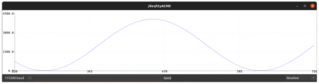
The code for the SAM-D21 is as follows, and the example output is shown in Figure 7.
#include <Arduino.h>

#define pinSpk A0
#define pinMic A1
int adcValue;

void setup() {
  SerialUSB.begin(115200);
  analogReadResolution(12);
  analogWriteResolution(10);

}

void loop() {
  int degree = 0;
  float radian = 0.0;
  float sineValue = 0.0;
  int dValue = 0;

  for (degree = 0; degree < 360; degree++) {

    radian = (float)degree * (2.0 * 3.1415926) / 360.0;
    sineValue = sin(radian);
    dValue = (int)((1.0+sineValue)*510.0);
    analogWrite( pinSpk, dValue);
    adcValue = analogRead(pinMic);
    SerialUSB.println(adcValue);
  }
}
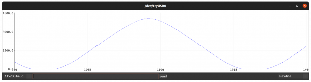
For ESP32, the program code is as follows. and the sample result is as shown in Figure 8.
#include <Arduino.h>

#define pinSpk 26
#define pinMic 36
int adcValue;

void setup() {
  Serial.begin(115200);
  analogReadResolution(12);
}

void loop() {
  int degree = 0;
  float radian = 0.0;
  float sineValue = 0.0;
  int dValue = 0;

  for (degree = 0; degree < 360; degree++) {
    radian = (float)degree * (2.0 * 3.1415926) / 360.0;
    sineValue = sin(radian);
    dValue = (int)((1.0 + sineValue) * 125.0);
    dacWrite( pinSpk, dValue );
    adcValue = analogRead(pinMic);
    Serial.println(adcValue);
  }
}
Conclusion
In this article, esp32’s ADC has some glitches that require compensation for more accurate output, and esp32’s DAC command uses dacWrite() instead of analogWrite(). The usage depends on many factors such as price, the need for a high-precision ADC, amount of RAM/ROM memory, etc. Finally, have fun with programming.
(C) 2020-2022, By Jarut Busarathid and Danai Jedsadathitikul
Updated 2022-01-23