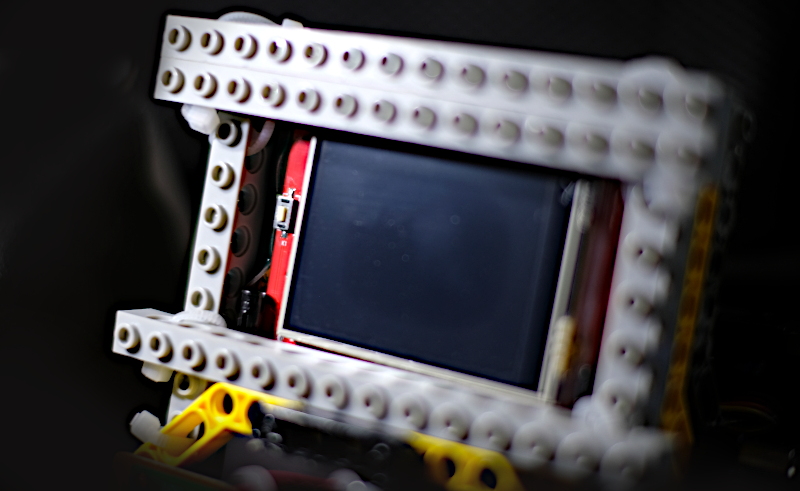
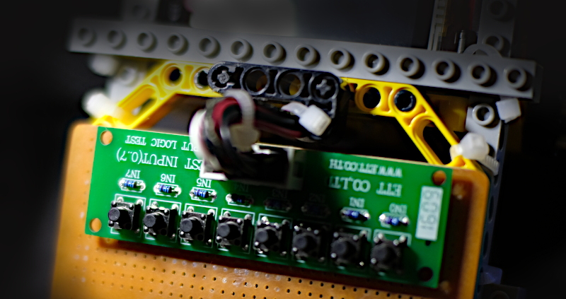
From the previous article that has used a 3.5″ display for Raspberry Pi Board to use with ESP32, we also have an Arduino 2.4″ TFT LCD & Touch Shield that is used with Arduino Uno and Arduino Mega (as shown in Figure 1. ) and want to use with a microcontroller STM32F401RET6 Board NUCLEO-F401RE and STM32F401CC (Figure 2), which are Cortex-M4 with 96KB and 64KB memory respectively, ROM memory is 512KB and 128KB, with 8 switches connected to the pin. In this article, Board ET-TEST 10P/INP (Figure 3) is used to replace the left, up, down, right, m1,m2, A and B buttons respectively.
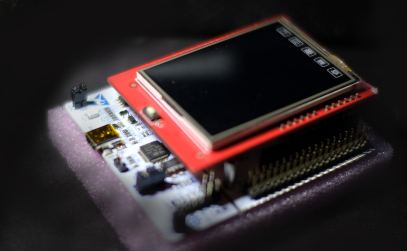
Arduino 2.4″ TFT LCD Shield Touch Screen
Properties
The properties of the display module are as follows.
- Display resolution 320×240 dots color.
- 16-bit color display or 65,535 colros
- 8-bit connection by receiving data from microcontroller via pin D0-D1.
- There is a control bus to operate from a microcontroller of 5 pins.
- RD, send read signal
- WR, send write signal
- DC, send signal that it will write
- RST, send reset signal
- CS, signals the module that it has been executed or not executed.
- The module driver chip is ili9341 (Figure 3) or ili9481 (Figure 4).
Circuit
Schematic diagram of the connection between the pins of the LCD module and the STM32F401 with the switch and the speaker as shown in Figure 5.
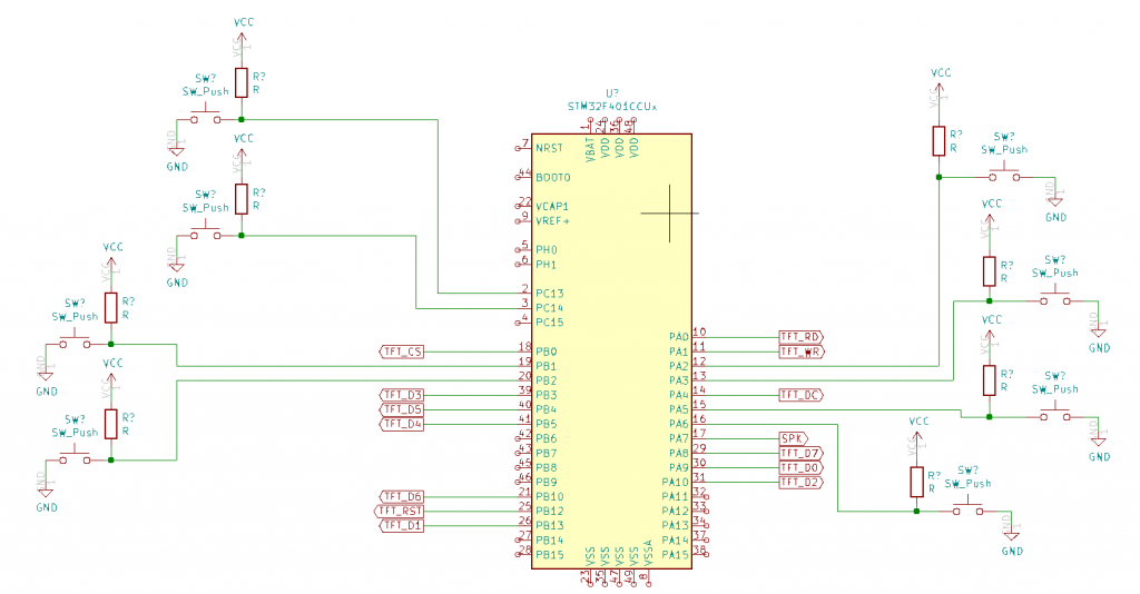
From Figure 5, they are connected as follows.
- TFT_CS connects with PB0
- TFT_RST connects with PB12
- TFT_RD connects with PA0
- TFT_WR connects with PA1
- TFT_DC connects with PA4
- SPK connects with PA7
- TFT_D0 connects with PA9
- TFT_D1 connects with PB13
- TFT_D2 connects with PA10
- TFT_D3 connects with PB3
- TFT_D4 connects with PB5
- TFT_D5 connects with PB4
- TFT_D6 connects with PB10
- TFT_D7 connects with PA8
- ET-TEST 10P/INP connects with:
- PC13
- PC14
- PB1
- PB2
- PA2
- PA3
- PA50
- PA6
TFT_eSPI‘s setting
The settings in the TFT_eSPI header file if the display module uses ILI9341 are as follows.
#define STM32
#define TFT_PARALLEL_8_BIT

#define ILI9341_DRIVER

#define TFT_CS   PB0
#define TFT_DC   PA4
#define TFT_RST  PB12

#define TFT_WR   PA1
#define TFT_RD   PA0

#define TFT_D0   PA9
#define TFT_D1   PB13
#define TFT_D2   PA10
#define TFT_D3   PB3
#define TFT_D4   PB5
#define TFT_D5   PB4
#define TFT_D6   PB10
#define TFT_D7   PA8

#define LOAD_GLCD   // Font 1. Original Adafruit 8 pixel font needs ~1820 bytes in FLASH
#define LOAD_FONT2  // Font 2. Small 16 pixel high font, needs ~3534 bytes in FLASH, 96 characters
#define LOAD_FONT4  // Font 4. Medium 26 pixel high font, needs ~5848 bytes in FLASH, 96 characters
#define SMOOTH_FONT
In the case that the TFT module driver is an ILI9481 chip, change the driver by setting the same settings as follows.
#define STM32
#define TFT_PARALLEL_8_BIT

#define ILI9481_DRIVER

#define TFT_CS   PB0  // Chip select control pin
#define TFT_DC   PA4  // Data Command control pin
#define TFT_RST  PB12 //PC1  // Reset pin ***

#define TFT_WR   PA1  // Write strobe control pin
#define TFT_RD   PA0  // Read pin

#define TFT_D0   PA9  // 8 bit parallel bus to TFT
#define TFT_D1   PB13 // PC7 // ***
#define TFT_D2   PA10
#define TFT_D3   PB3
#define TFT_D4   PB5
#define TFT_D5   PB4
#define TFT_D6   PB10
#define TFT_D7   PA8

#define LOAD_GLCD   // Font 1. Original Adafruit 8 pixel font needs ~1820 bytes in FLASH
#define LOAD_FONT2  // Font 2. Small 16 pixel high font, needs ~3534 bytes in FLASH, 96 characters
#define LOAD_FONT4  // Font 4. Medium 26 pixel high font, needs ~5848 bytes in FLASH, 96 characters
#define SMOOTH_FONT
Example Code
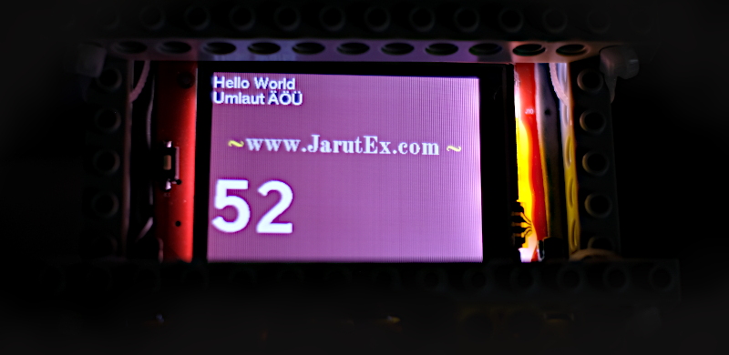
An example of a display test program using the library U8g2_for_TFT_eSPI. It is a library that works through the layer of TFT_eSPI (available here) and use the hello example of the library to add a set of instructions to use it as shown in Figure 6.
/*
  Hello.ino

  Demonstrates how to use U8g2_for_TFT_eSPI library.

  U8g2_for_TFT_eSPI:
    - Use U8g2 fonts with TFT_eSPI
    - Supports UTF-8 in print statement
    - 90, 180 and 270 degree text direction

  List of all U8g2 fonts:    https://github.com/olikraus/u8g2/wiki/fntlistall

  TFT_eSPI library:          https://github.com/Bodmer/TFT_eSPI
  U8g2_for_TFT_eSPI library: https://github.com/Bodmer/U8g2_for_TFT_eSPI

*/
#include "SPI.h"
#include "TFT_eSPI.h"
#include "U8g2_for_TFT_eSPI.h"

TFT_eSPI tft = TFT_eSPI();   // tft instance
U8g2_for_TFT_eSPI u8f;       // U8g2 font instance

void setup() {
  tft.begin();
  tft.setRotation(1);
  tft.fillScreen(0x3861);

  u8f.begin(tft);
}

unsigned long x = 0;

void loop() {
  u8f.setFontMode(0);
  u8f.setFontDirection(0);
  u8f.setForegroundColor(TFT_WHITE);

  u8f.setFont(u8g2_font_helvR14_tf);
  u8f.setCursor(0,20);
  u8f.print("Hello World");
  u8f.setCursor(0,40);
  u8f.print("Umlaut ÄÖÜ");

  u8f.setBackgroundColor(0x3861);
  u8f.setForegroundColor(0xe717);
  u8f.setFont(u8g2_font_osb21_tf);
  u8f.setCursor(40,100);
  u8f.print("www.JarutEx.com");
  u8f.setForegroundColor(TFT_YELLOW);
  u8f.setCursor(20,100);
  u8f.print("~");
  u8f.setCursor(280,100);
  u8f.print("~");

  u8f.setFont(u8g2_font_inb63_mn);
  u8f.setFontMode(0);
  u8f.setForegroundColor(TFT_WHITE);

  while (1) {
    u8f.setCursor(0,200);
    u8f.print(x);
    x++;
    if (x > 99999) {
      x = 0;
    }
    delay(1000);
  }
}
From the sample code, here’s an interesting statement:
- begin( tft ) means the library requires a tft, a TFT_eSPI object, to be used to draw characters and is the default library command of U8g_for_TFT_eSPI.
- setFontMode(0) means it’s a drawing over the background.
- setFontMode(1) means to drawing only the color point of the letters.
- setFontDirection(x) means to set the direction of drawing characters (Try changing the x value from 0 to another value.)
- setFont( x ) means choose to use the letter x which previews the character and values from this web page.
- setForegroundColor( c ) means set the font color to c
- setBackgroundColor( c ) means set the background color of the letter to c.
- setCursor( x, y ) means to set the starting point to draw the character at the coordinates (x,y), which is the position at the bottom left of the letter drawing.
- print(x) means to display text x according to the font, color, background color, drawing method, and position as defined in the previous command.
Conclusion
From this article, it is found that using a parallel connection requires more pins than using the SPI bus, but when you look at the TFT_eSPI setting, you don’t need to set the clock frequency. As a result, the overall transmission speed may be higher than SPI. At the same frequency, SPI takes time to decode the bits from serial to parallel because the data was sent bit by bit but the implementation must apply the whole byte while parallel transmission sends one byte at a time.
In addition, the use of TFT_eSPI has been found to support the use of various display models and achieve very good operating speeds. But the weakness of the library is that there are few fonts to choose from or have to make fonts to use by yourself. When executing the library U8g_for_TFT_eSPI, you will find that there are many types of fonts to use and a variety of formats. The thing that must be careful is the amount of system memory remaining and how to draw from the bottom up hence the value passed to the command setCursor(x,y), the y value will be the bottom of the draw, not the top like it used to.
Finally, have fun with programming.
If you want to talk with us, feel free to leave comments below!!!
(C) 2020-2021, BY Jarut Busarathid and Danai Jedsadathitikul
Updated 2021-12-26