This article introduces the motion sensor module or moving in the digital 3 axes using the IC MMA7660FC that was written in the previous article to attach with the Raspberry Pi board and write a Python program to connect and read the values to display.
Equipment
- Raspberry Pi generation 2/3 or 4
- MMA7660FC module
Get to know GPIO
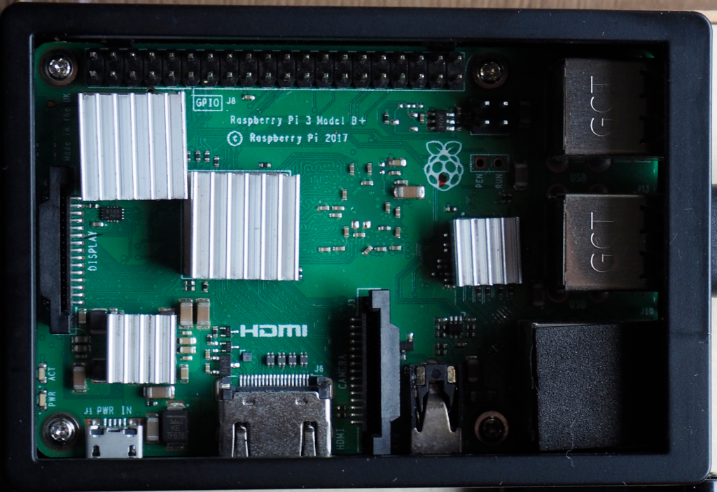
Before getting started with the mma7660FC module, it is important to understand the GPIO or pin connections of the Raspberry Pi board. The most useful command is the gpio command.
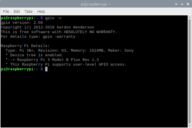
You can check the version and properties of the board in use by typing gpio -v , after which the program reported the version with details about the board, the amount of memory of the board as shown in Figure 4.
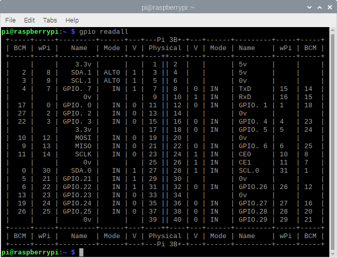
If you want to know what each GPIO pin does, you can use the command gpio readall to report the role of the pin as shown in Figure 5. In this article, we choose to connect to the Raspberry Pi board via the I2C bus channel 1.
I2C bus activation
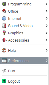
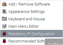
To use the I2C bus of the Raspberry Pi Board, you need to enable access permission by going to the main menu and selecting the menu Preferences as shown in Figure 6 then select the sub-menu Raspberry Pi Configuration as shown in Figure 7, there will be a window Program as shown in Figure 8.
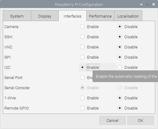
From Figure 8, select the interfaces tab and select Enable in the I2C section to enable permission or access to the Raspberry Pi board’s I2C bus. After enabling the I2C bus, click the OK button and reboot the Raspberry Pi board to ensure that the bus is ready for use.
Connection
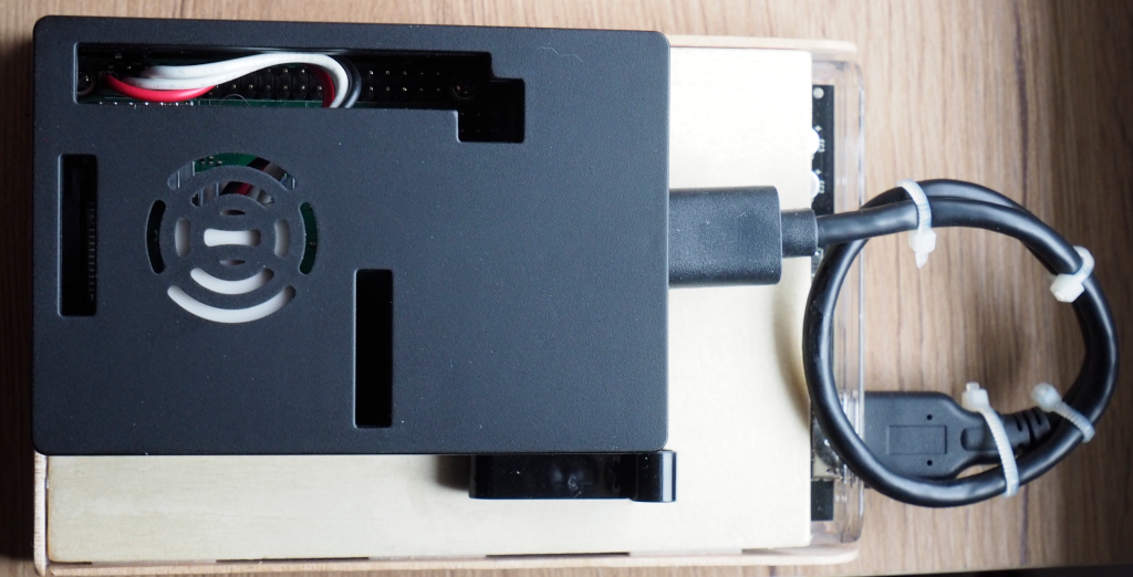
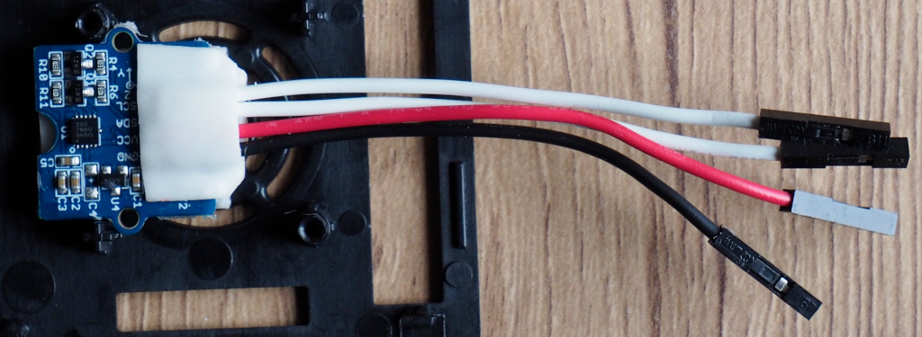
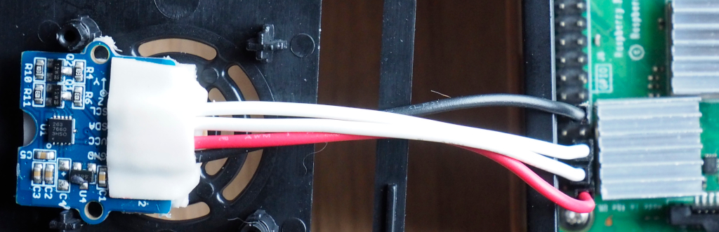
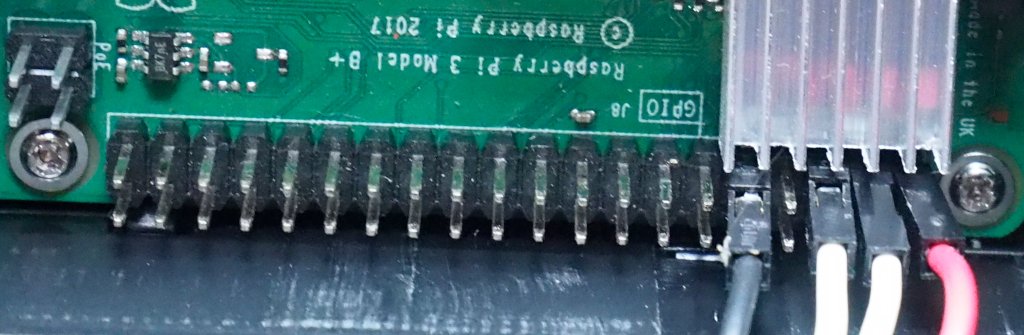
Connecting the sensor module to the Raspberry Pi Board via the I2C Bus Channel 1 is shown in Figures 9 and 10 by connecting both pins according to the following table.
| Module | Raspberry Pi’s gpio |
|---|---|
| VCC | 3V3 |
| GND | GND |
| SDA | SDA.1 |
| SCL | SCL.1 |
Check the connection results
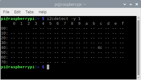
After the sensor module is connected to the Raspberry Pi board’s GPIO, verify the connection results by calling the i2cdetect -y 1 command to specify a connection check on the I2C Channel 1 as shown in Figure 11, where the device is located at 4c or 0x4c, which is the location of the sensor module connected to the Raspberry Pi board.
Example code
The example program code16-1 has a generated the MMA7660FC class, which is adapted from the previous example by changing the command to be the command of the Raspberry Pi board, it is found that activating the I2C bus requires a library named smbus. After that, an object for reference to the I2C bus must be created as follows.
object = smbus.SMBus( current I2C channel )
Writing data to the I2C bus has the following patterns.
object.write_byte_data(
device address,
command,
data
)
Reading multibyte data from the I2C bus has the following patterns.
result = object.read_i2c_block_data(
device address,
command,
byte(s) read
)
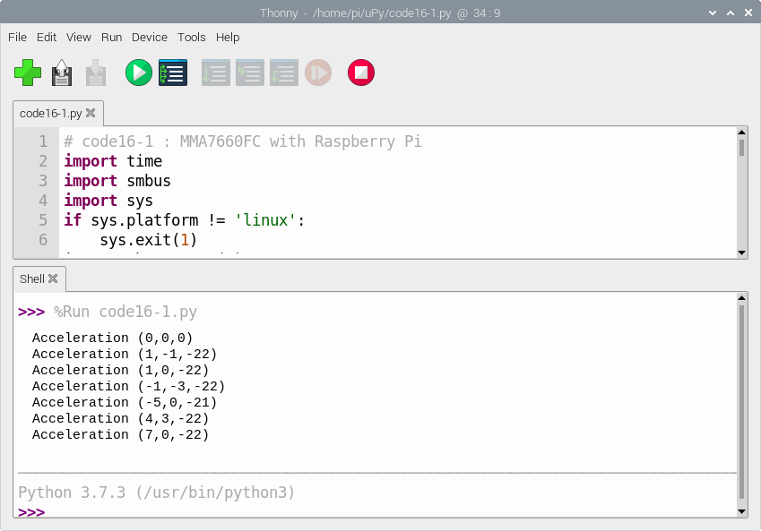
when the program runs while the correct circuit is connected, the result will be displayed as shown in Figure 12.
# code16-1 : MMA7660FC with Raspberry Pi
import time
import smbus
import sys
if sys.platform != 'linux':
    sys.exit(1)
i2c = smbus.SMBus(1)
class MMA7660FC:
    def __init__(self, i2c, addr=0x4c):
        self.i2c = i2c
        self.mma7660fcAddr = addr
        self.i2c.write_byte_data( self.mma7660fcAddr, 0x07, 0x01 )
        self.i2c.write_byte_data( self.mma7660fcAddr, 0x08, 0x07 )
        time.sleep(0.01)
    def read(self):
        data = self.i2c.read_i2c_block_data(self.mma7660fcAddr, 0x00, 3)
        # Convert the data to 6-bits
        xAccl = data[0] & 0x3F
        if xAccl > 31 :
            xAccl -= 64
        yAccl = data[1] & 0x3F
        if yAccl > 31 :
            yAccl -= 64
        zAccl = data[2] & 0x3F
        if zAccl > 31 :
            zAccl -= 64
        return (xAccl,  yAccl,  zAccl)

if __name__=='__main__':
    sensor = MMA7660FC(i2c)
    while True:
        sData = sensor.read()
        print("Acceleration ({},{},{})".format(sData[0],sData[1],sData[2] ))
        time.sleep(1)
Conclusion
From this article, we founded that using the sensor module on the Raspberry Pi board is different from that with the ESP8266 in terms of connecting pins, activating the I2C bus and libraries as the ESP8266 uses a MicroPython which truncated from Python 3 and adds a number of drivers and libraries optimized for lower memory, storage and operating power devices. However, When observing the code, you will find that the writing principle or algorithm of the program remains the same. This makes it easy to switch from one platform to another which is an advantage of developing work with Python.
Finally, our team hope that this article will be more or less helpful for those who are interested.
Have fun with programming.
(C) 2020, Jarut Busarathid and Danai Jedsadathitikul
Updated 2021-07-04