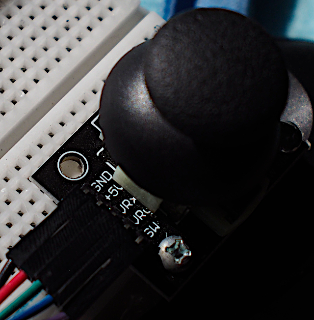
This article is programming to write a program to use the joystick module as shown in Figure 1, in which the module can tell the X-axis movement, Y-axis movement, and the state of pressing the switch on the joystick. An example of this module is to use the esp32 board using C++ to connect to the GPIO using the commands mentioned in this article.

Joystick Module
The joystick module from Figure 1 is a popular joystick used with game consoles. It has a 2-axis analog sensor for reading in the X and Y axes. This is different from using a digital switch that only knows its pressed or unpressed state. While analog provides the resolution according to the resolution of the microcontroller ADC (Analog to Digital Converter) circuit, for example, 8-bit ADC gives values from 0 to 255 and 10-bit ADC gives values in the range 0 to 1023, etc. Using this module must choose a microcontroller that has at least 2 channels or 2 ADC pins. When reading from the sensor, the values are as follows.
- Minimum represents being on the left or bottom, which is the value Xmin and Ymin
- Maximum represents being on the right or top, which is the value Xmax and Ymax
- The middle value when the lever is not moved, which is the value of Xcenter and Ycenter
Connecting to the module must be connected via 5 pins as shown in Figure 2. Connecting to ESP32 is done as in the following table.
| Joystick | ESP32 |
|---|---|
| VRX | SN or VN or IO39 |
| VRY | SP or VP or IO36 |
| SW | IO16 |
| +5VDC | 3V3 |
| GND | GND |
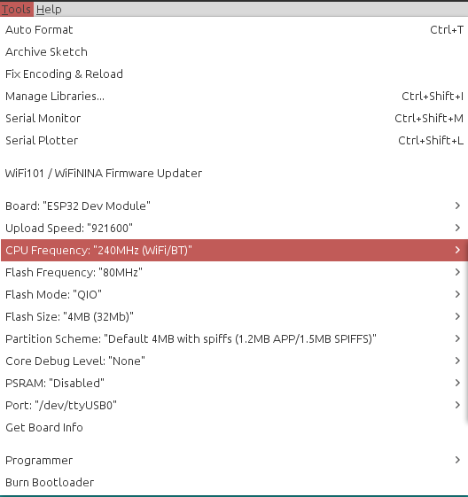
The settings of the Arduino IDE are as shown in Figure 3.
Example Code
An example program reads the X and Y-axis coordinates and the lever switch status is as follows.
#define VR_X_PIN 39
#define VR_Y_PIN 36
#define SW_PIN 16
void setup() {
Serial.begin(115200);
pinMode( SW_PIN, INPUT_PULLUP );
}
void doUpdate() {
uint16_t x = analogRead( VR_X_PIN );
uint16_t y = analogRead( VR_Y_PIN );
bool sw = digitalRead( SW_PIN );
Serial.print(x);
Serial.print(" ");
Serial.print(y);
Serial.print(" ");
Serial.println(sw);
}
void loop() {
doUpdate();
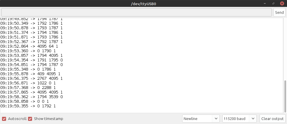
delay(500);
}The result from the sample program is shown in Figure 4.
For Python can be written as follows
###########################################################
# Joystick module + ESP32 + MicroPython
# By JarutEx (https://www.jarutex.com)
###########################################################
from machine import Pin, ADC
import time
import machine as mc

mc.freq(240000000)
vrx = ADC(Pin(39, Pin.IN))
vrx.atten(ADC.ATTN_11DB)       #Full range: 3.3v
vry = ADC(Pin(36, Pin.IN))
vry.atten(ADC.ATTN_11DB)       #Full range: 3.3v
sw = Pin(16, Pin.IN, Pin.PULL_UP)

def doUpdate():
    vrxValue = vrx.read()
    vryValue = vry.read()
    swValue = sw.value()
    print("({},{}):{}".format(vrxValue,vryValue,swValue))

while True:
    doUpdate()
    time.sleep_ms(500)
Conclusion
From this article, you will find that reading data from the joystick module requires two ADC pins for reading the values of the X and Y axes. When used with a microcontroller that has a high resolution of the ADC sector, it will give more detailed values. It can be better interpreted for the value of movement. Finally, have fun with programming.
If you want to discuss or talk with us, feel free to comments below!!!
If you want to talk with us, feel free to comments below !!
References
- PS2 XY Joystick Module
- JoyStick Breakout Module Shield for PS2 Joystick Game Controller For Arduino
- ADC WiKiPedia
- ESP32-DEV-KIT
(C) 2020-2021, By Jarut Busarathid and Danai Jedsadathitikul
Updated 2021-10-16