This article is a series of programming articles focused on the Cortex-M0 via the STM32F030F4P6 or any other STM32 microcontroller based on CMSIS, an ARM firmware compiled from vivonomicon.com‘s series of Bare Metal: STM32 Programming articles without using the Arduino framework. In the article EP.1 is a matter of preparation. It consists of creating a link file to link different parts of the code together and the working part file. After that, the result file is uploaded into the microcontroller to complete the program development process.
Equipments
- ARM none eabi tool chain
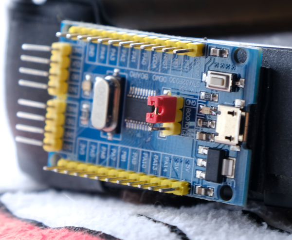
- Boards that use Cortex-M0 microcontrollers such as
- STM32F030F4P6
- STM32F0 DISCOVERY
- For Cortex-M3 such as ET-STM32F103 /Cortex-M4
- ST-Link/V2 or USB-RS232 or if it is Board ET-STM32F103, use USB2RS232 converter with RS232 cable.
- Computers and operating systems that can install ARM none eabi tool chain, which we use Computer Notebook with Intel N5000 processor, 4GB of RAM, installed Linux MINT 20.2 operating system as shown in Figure 2.

Program development process
The procedure for developing a program for use with an ARM microcontroller is as follows.
- Prepare a .ld file for defining links to create programs.
- Write assembly language code in a .S or .s file to prepare the system startup.
- Write code in C language
- Compile the program code to generate .obj.
- Link to integrate .obj with libraries as defined in .ld.
- Upload the program to the board
Composition of files based on CMSIS-Core
The files that must be run in the written program include:
- device.h
- system_device.h
- core_cpu.h
- cmsis_compiler.h
The files used to link include
- Program developed (with main() )
- startup_xxx.S หรือ startup_xxx.c
- system_xxx.c
Composition of files based on CMSIS Embedded Application
The executable files in the written program include:
- device.h
The files used to link include
- startup_<device>.c or .S
- system_<device>.c
- Program developed (with main() )
Prepare files for linking
The .ld file for linking is used to define the memory location and memory size of the microcontroller. The value for stm32f030f4p6 is as follows and save it to a file named STM32F030F4P6.ld
/* Label for the program's entry point */
    ENTRY(reset_handler)
    /* End of RAM / Start of stack  (4KB SRAM) */
    _estack = 0x20001000;

    _Min_Leftover_RAM = 0x400;
    MEMORY
    {
      FLASH ( rx )      : ORIGIN = 0x08000000, LENGTH = 16K
      RAM ( rxw )       : ORIGIN = 0x20000000, LENGTH = 4K
    }
    SECTIONS
    {
      /* The vector table goes at the start of flash. */
      .vector_table :
      {
        . = ALIGN(4);
        KEEP (*(.vector_table))
        . = ALIGN(4);
      } >FLASH
      /* The 'text' section contains the main program code. */
      .text :
      {
        . = ALIGN(4);
        *(.text)
        *(.text*)
        . = ALIGN(4);
      } >FLASH
      /* The 'rodata' section contains read-only data,
       * constants, strings, information that won't change. */
      .rodata :
      {
        . = ALIGN(4);
        *(.rodata)
        *(.rodata*)
        . = ALIGN(4);
      } >FLASH
      /* The 'data' section is space set aside in RAM for
       * things like variables, which can change. */
      _sidata = .;
      .data : AT(_sidata)
      {
        . = ALIGN(4);
        /* Mark start/end locations for the 'data' section. */
        _sdata = .;
        *(.data)
        *(.data*)
        _edata = .;
        . = ALIGN(4);
      } >RAM
      /* The 'bss' section is similar to the 'data' section,
       * but its space is initialized to all 0s at the
       * start of the program. */
      .bss :
      {
        . = ALIGN(4);
        /* Also mark the start/end of the BSS section. */
        _sbss = .;
        *(.bss)
        *(.bss*)
        *(COMMON)
        . = ALIGN(4);
        _ebss = .;
      } >RAM
      /* Space set aside for the application's heap/stack. */
      .dynamic_allocations :
      {
        . = ALIGN(4);
        _ssystem_ram = .;
        . = . + _Min_Leftover_RAM;
        . = ALIGN(4);
        _esystem_ram = .;
      } >RAM
    }
From the file it is found that the RAM is 4kB, the ROM is 16kB, the default location of RAM or SRAM is 0x20000000 and ROM or FLASH ROM is 0x8000000, and _estack is the end of the memory stack, which is set to 0x20001000, has an additional SECTIONS section. Each section in SECTIONS begins with
.vector_table for defining about vector tables
.text for define program storage memory, which is flash memory.
.data for defining the storage memory
.bss for defining memory stack
.dynamic_allocations for defining dynamic memory reservations.
Vector table
The vector table is part of the interrupt response schedule. Used to specify the location of the subprogram that was called when an interrupt event occurred. The data of this table is stored in a file named vector_table.S which is an assembly language file (.s or .S to indicate that it is an assembly language file), as in the following example.
.syntax unified
.cpu cortex-m0
.fpu softvfp
.thumb

.global vtable
.global default_interrupt_handler

.type vtable, %object
.section .vector_table,"a",%progbits
vtable:
  // 0-15
  .word _estack
  .word reset_handler
  .word NMI_handler
  .word hard_fault_handler
  .word 0
  .word 0
  .word 0
  .word 0
  .word 0
  .word 0
  .word 0
  .word SVC_handler
  .word 0
  .word 0
  .word pending_SV_handler
  .word SysTick_handler
  // 16-31
  .word window_watchdog_IRQ_handler
  .word PVD_IRQ_handler
  .word RTC_IRQ_handler
  .word flash_IRQ_handler
  .word RCC_IRQ_handler
  .word EXTI0_1_IRQ_handler
  .word EXTI2_3_IRQ_handler
  .word EXTI4_15_IRQ_handler
  .word 0
  .word DMA1_chan1_IRQ_handler
  .word DMA1_chan2_3_IRQ_handler
  .word DMA1_chan4_5_IRQ_handler
  .word ADC1_IRQ_handler
  .word TIM1_break_IRQ_handler
  .word TIM1_CC_IRQ_handler
  .word TIM2_IRQ_handler
  // 32-47
  .word TIM3_IRQ_handler
  .word 0
  .word 0
  .word TIM14_IRQ_handler
  .word 0
  .word TIM16_IRQ_handler
  .word TIM17_IRQ_handler
  .word I2C1_IRQ_handler
  .word 0
  .word SPI1_IRQ_handler
  .word 0
  .word USART1_IRQ_handler
  .word 0
  .word 0
  .word 0
  .word 0
  // 48
  // (Location to boot from for RAM startup)
  #define boot_ram_base  0xF108F85F
  .word boot_ram_base

  .weak NMI_handler
  .thumb_set NMI_handler,default_interrupt_handler
  .weak hard_fault_handler
  .thumb_set hard_fault_handler,default_interrupt_handler
  .weak SVC_handler
  .thumb_set SVC_handler,default_interrupt_handler
  .weak pending_SV_handler
  .thumb_set pending_SV_handler,default_interrupt_handler
  .weak SysTick_handler
  .thumb_set SysTick_handler,default_interrupt_handler
  .weak window_watchdog_IRQ_handler
  .thumb_set window_watchdog_IRQ_handler,default_interrupt_handler
  .weak PVD_IRQ_handler
  .thumb_set PVD_IRQ_handler,default_interrupt_handler
  .weak RTC_IRQ_handler
  .thumb_set RTC_IRQ_handler,default_interrupt_handler
  .weak flash_IRQ_handler
  .thumb_set flash_IRQ_handler,default_interrupt_handler
  .weak RCC_IRQ_handler
  .thumb_set RCC_IRQ_handler,default_interrupt_handler
  .weak EXTI0_1_IRQ_handler
  .thumb_set EXTI0_1_IRQ_handler,default_interrupt_handler
  .weak EXTI2_3_IRQ_handler
  .thumb_set EXTI2_3_IRQ_handler,default_interrupt_handler
  .weak EXTI4_15_IRQ_handler
  .thumb_set EXTI4_15_IRQ_handler,default_interrupt_handler
  .weak DMA1_chan1_IRQ_handler
  .thumb_set DMA1_chan1_IRQ_handler,default_interrupt_handler
  .weak DMA1_chan2_3_IRQ_handler
  .thumb_set DMA1_chan2_3_IRQ_handler,default_interrupt_handler
  .weak DMA1_chan4_5_IRQ_handler
  .thumb_set DMA1_chan4_5_IRQ_handler,default_interrupt_handler
  .weak ADC1_IRQ_handler
  .thumb_set ADC1_IRQ_handler,default_interrupt_handler
  .weak TIM1_break_IRQ_handler
  .thumb_set TIM1_break_IRQ_handler,default_interrupt_handler
  .weak TIM1_CC_IRQ_handler
  .thumb_set TIM1_CC_IRQ_handler,default_interrupt_handler
  .weak TIM2_IRQ_handler
  .thumb_set TIM2_IRQ_handler,default_interrupt_handler
  .weak TIM3_IRQ_handler
  .thumb_set TIM3_IRQ_handler,default_interrupt_handler
  .weak TIM14_IRQ_handler
  .thumb_set TIM14_IRQ_handler,default_interrupt_handler
  .weak TIM16_IRQ_handler
  .thumb_set TIM16_IRQ_handler,default_interrupt_handler
  .weak TIM17_IRQ_handler
  .thumb_set TIM17_IRQ_handler,default_interrupt_handler
  .weak I2C1_IRQ_handler
  .thumb_set I2C1_IRQ_handler,default_interrupt_handler
  .weak SPI1_IRQ_handler
  .thumb_set SPI1_IRQ_handler,default_interrupt_handler
  .weak USART1_IRQ_handler
  .thumb_set USART1_IRQ_handler,default_interrupt_handler
.size vtable, .-vtable

.section .text.default_interrupt_handler,"ax",%progbits
default_interrupt_handler:
  default_interrupt_loop:
    B default_interrupt_loop
.size default_interrupt_handler, .-default_interrupt_handler
In the above code, the processor is defined as cortex-m0, and the floating-point processor is used as the software (softvfp), and in the vector table (.type vtable) the stack position and reset_handler both of which are word (.word) or 4 bytes size integer values.
Main program
The main program consists of two parts: the start-up part when the microcontroller is ready after a system reset event and the part of programming with C language. The first part is written in assembly language because it requires access to hardware functions that C language cannot and prepare the default function to run the part of the program written in C language. It specifies a function called main in the C language.
Start part
The main program is as follows. Save it to a file called core.S for startup and specify a call to the main function written in C and perform an endless loop with B or jump to the LoopForever label.
.syntax unified
.cpu cortex-m0
.fpu softvfp
.thumb

.global reset_handler
.type reset_handler, %function
reset_handler:
  LDR  r0, =_estack
  MOV  sp, r0
  MOVS r0, #0
// Load the start/end addresses of the data section,
// and the start of the data init section.
  LDR  r1, =_sdata
  LDR  r2, =_edata
  LDR  r3, =_sidata
  B    copy_sidata_loop

copy_sidata:
  // Offset the data init section by our copy progress.
  LDR  r4, [r3, r0]
  // Copy the current word into data, and increment.
  STR  r4, [r1, r0]
  ADDS r0, r0, #4

copy_sidata_loop:
  // Unless we've copied the whole data section, copy the
  // next word from sidata->data.
  ADDS r4, r0, r1
  CMP  r4, r2
  BCC  copy_sidata

// Once we are done copying the data section into RAM,
// move on to filling the BSS section with 0s.
  MOVS r0, #0
  LDR  r1, =_sbss
  LDR  r2, =_ebss
  B    reset_bss_loop

// Fill the BSS segment with '0's.
reset_bss:
  // Store a 0 and increment by a word.
  STR  r0, [r1]
  ADDS r1, r1, #4

reset_bss_loop:
  // We'll use R1 to count progress here; if we aren't
  // done, reset the next word and increment.
  CMP  r1, r2
  BCC  reset_bss


  B    main
LoopForever:
  B    LoopForever
.size reset_handler, .-reset_handler
C language
Now only the part of the C language is left to be written. An example for a start is as follows. You will find that we do nothing Because connecting to external devices or Peripheral requires running the firmware or the library of the chip manufacturing company to run it with the code we wrote.
int main(void) {

}
Compile program
The test compile program consists of compiling the core.S, vector_table.S, and main.c files.
arm-none-eabi-gcc \
-x assembler-with-cpp -c -O0 \
-mcpu=cortex-m0 -mthumb -Wall \
core.S -o core.o
arm-none-eabi-gcc \
-x assembler-with-cpp -c -O0 \
-mcpu=cortex-m0 -mthumb -Wall \
vector_table.S -o vector_table.o
arm-none-eabi-gcc -c \
-mcpu=cortex-m0 -mthumb -Wall -g \
-fmessage-length=0 --specs=nosys.specs \
main.c -o main.o
Upon successful completion, you will receive a core.o file for preliminary defining when the program is executed and load function main written in C language vector_table.o is the call back to the interrupt response function and main.o is the compiled C code file. Once all three files are obtained without any errors, the next step is to merge all three files under the terms of the script link by the following commands.
arm-none-eabi-gcc \
core.o vector_table.o main.o \
-mcpu=cortex-m0 \
-mthumb -Wall --specs=nosys.specs \
-nostdlib -lgcc -T./STM32F030F4P6.ld \
-o main.elf
Upload program
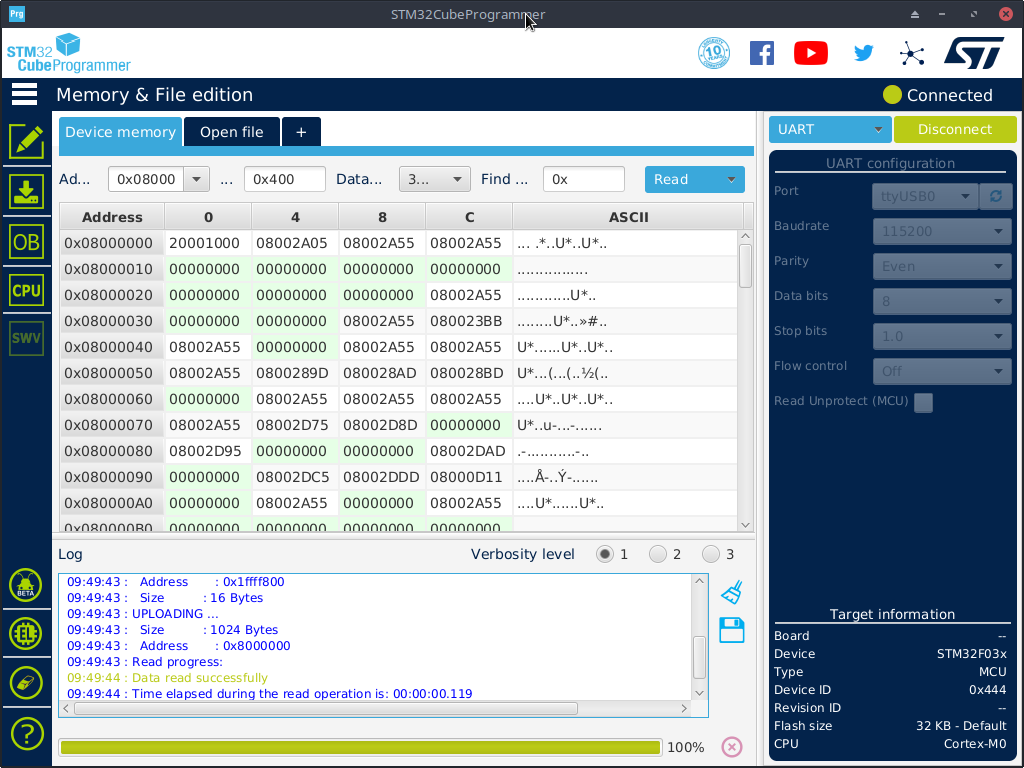
When successful, you will get the main.elf file which is the file of all programs written and ready to be uploaded into the microcontroller with the program STM32CubeProgrammer. This ended the beginning of our programming life with STM32F030F4P6 as shown in Figures 3, 4, 5, 6, 7 and 8.

From Figure 3, select the type of connection to match the device. We choose UART or work through a USB to RS232 converter and choose the correct connection port. Before connecting (before pressing the connect button), it must boot into the chip program load by selecting BOOT0 as VCC and press the Reset switch when pressing the Connect button of the STM32CubeProgrammer It will connect. When the connection is successful, it will display the message “Connected” as shown in Figure 4. And the Connect button. Change the message to Disconnect to use to disconnect the connection.
Note
In the case of using other types, the procedure is the same, namely choosing the type of connection, specify the communication port, set the communication speed Then connect to the device.
From Figure 4, click the Erasing & Programming icon (the image following the pencil or pen-like image) will display the screen as shown in Figure 5. In this step, you need to select the compiled program file by clicking the Browse button and the Figure 6 will be displayed, select the main.elf file and click Open.
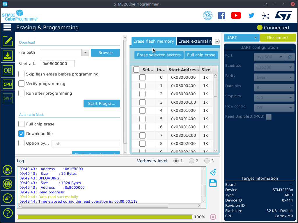

When opening the program file used for upload (the program STM32CubeProgramming uses the word Download) into the microcontroller, click the Start Program button to enter the chip writing process. (Usually, we prefer to click on the Full chip erase button first to ensure that all data in the ROM has been erased). If successful, it will display a window as shown in Figure 7, and then click on the Disconnect button to cancel the connection, it will cause the Disconnect button to change to Connect as shown in Figure 8.


Conclusion
From this article, you will find that the process of programming bare metal or writing with a chip development kit without using Arduino’s tools has more steps. This is because the guy who made a bare metal framework kit to make it compatible with Arduino hid these steps to make it more convenient for beginners to programs. For this reason, it was found that the popularity of using Arduino is high, but when programming with a microcontroller that the Arduino development kit does not yet support or supports, but does not cover all functions, the developer’s possible option is to return to bare metal and for the ESP32 is to revert to the ESP-IDF as a last resort. Finally, have fun programming.
If you want to talk with us, feel free to leave comments below!!
References
- bare-metal-stm32-programming-part-1-hello-arm @vivonomicon.com
- STM32F030F4 Mainstream Arm Cortex-M0 Value line MCU with 16 Kbytes of Flash memory, 48 MHz CPU
- Startup File startup_<device>.c
- Startup File startup_<device>.s (deprecated)
- System Configuration Files system_<device>.c and system_<device>.h
- Device Header File <device.h>
(C) 2020-2021, By Jarut Busarathid and Danai Jedsadathitikul
Updated 2021-10-21