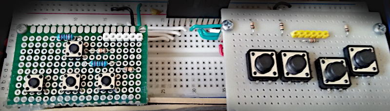
This article discusses the use of the ESP32’s GPIO to act as a digital signal import. By using the circuit of a keypad that is a switch of 8 that is made to look like a gamepad as in Figure 1.
Project structure
The structure of the ESP-IDF project is as shown in Figure 2. In the project directory, there are files CMakeList.txt and sdkconfig with a directory named main to store the project source code. The directory contains the C language files and CMakeLists.txt.

From the structure in Figure 2, the CMakeLists.txt file’s code must be generated as follows, in which the code content defines the minimum version of cmake program and configures the default cmake implementation according to the original ESP-IDF and names the project as ep05.
cmake_minimum_required(VERSION 3.5)
include($ENV{IDF_PATH}/tools/cmake/project.cmake)
project(ep05)
What writes main/CMakeLists.txt is as follows to define a list of files to be compiled. This is defined as main.c and sets the directory where the header file is stored, meaning it is either the same as main.c or in the main directory.
idf_component_register(SRCS "main.c"
                    INCLUDE_DIRS "")
When creating a structure like Figure 2, select the target of the system to be ESP32 as follows:
idf.py set-target esp32
The sdkconfig is created by running the following command idf.py menuconfig.
idf.py menuconfig
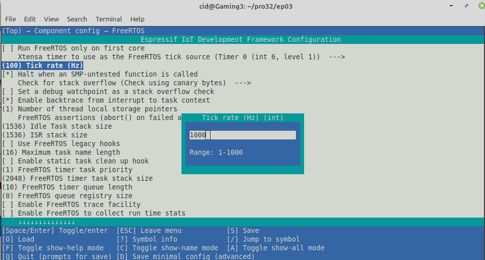
From the configuration screen, go to Component Config –> FreeRTOS and set the tick rate (Hz) to 1000 as shown in Figure 3, then save and exit the settings.
Commands
The GPIO implementation requires importing a header file named gpio.h located in the driver subfolder of the ESP-IDF, which can be imported with the include command:
#include <driver/gpio.h>
Pin selection must be specified with the following command.
gpio_pad_select_gpio( pin )
Commands for determining the functions of the pins. It has the following format: by the mode of the pins as GPIO_MODE_INPUT or GPIO_MODE_OUTPUT.
gpio_set_direction( pin, pinMode )
The command for reading a digital signal from a specified pin number has the following format:
digital_signal = gpio_get_level( pin )
Finally, the command to determine the format of the input signal in case of PULL UP is to use the following command:
gpio_pullup_en( pin )
To cancel PULL UP, run gpio_pullup_dis() as follows:
gpio_pullup_dis( pin )
If you want to use other GPIOs, you can read more articles as follows.
Example Code
The LED circuit used in this experiment is shown in Figure 4. The equipment used in the experiment are:
- esp32
- Experiment board
- Switch
- Resister

Code
#include <stdio.h>
#include <time.h>
#include <string.h>
#include <math.h>
#include "driver/gpio.h"
#include "sdkconfig.h"
#include "freertos/FreeRTOS.h"
#include "freertos/task.h"

#define swC 35
#define swD 34
#define swA 33
#define swB 32
#define keL 19
#define keU 18
#define keD 17
#define keR 16
gpio_num_t keys[] = {keL, keU, keD, keR, swC, swD, swA, swB};

void app_main(void)
{
  printf("Ep.05 Keypad\n");
  for (int i=0; i<8; i++) {
    gpio_pad_select_gpio(keys[i]);
    gpio_pullup_en(keys[i]);
    if (gpio_set_direction(keys[i], GPIO_MODE_INPUT) == ESP_OK) {
      printf("GPIO%02d ... Success.\n",keys[i]);
    } else {
      printf("GPIO%02d ... Parameter error.\n",keys[i]);
    }
  }
  vTaskDelay( 1000/portTICK_PERIOD_MS );

  while(1) {
    printf("%d:%d:%d:%d %d-%d %d-%d\n",
      gpio_get_level(keys[0]),
      gpio_get_level(keys[1]),
      gpio_get_level(keys[2]),
      gpio_get_level(keys[3]),
      gpio_get_level(keys[4]),
      gpio_get_level(keys[5]),
      gpio_get_level(keys[6]),
      gpio_get_level(keys[7])
    );
    vTaskDelay( 100/portTICK_PERIOD_MS );
  }
}
Compile and upload
Compile, then flash it into the chip and run the Serial Monitor program as follows:
idf.py -p /dev/ttyUSB0 build flash monitor
Result is as shown in Figure 5
idf.py -p /dev/ttyUSB0 flash

Conclusion
From this article, you will find that digital signal import is done using command gpio_get_level() and when using a pull-up circuit, call the command gpio_pullup_en() and cancel with the command gpio_pullup_dis(). Finally, have fun with programming.
If you want to talk with us, feel free to leave comments below!!
Reference
- ESP-IDF : GPIO & RTC GPIO
(C) 2020-2021, By Jarut Busarathid and Danai Jedsadathitikul
Updated 2021-12-27