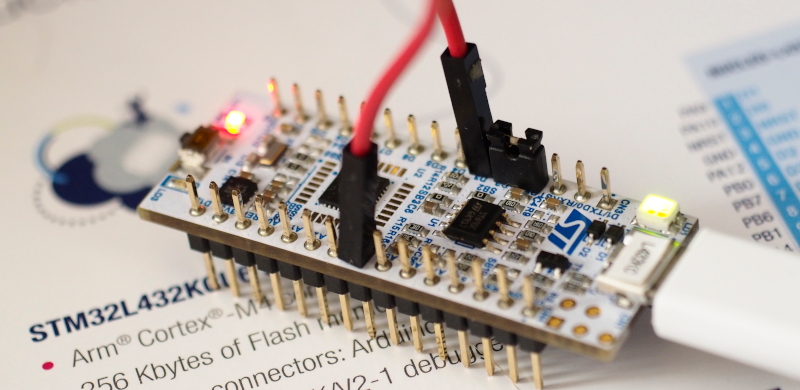
From reading the article Using STM32 Core Support for Arduino for Board Nucleo L432KC by Ajarn Rewat Siriphokapirom, we have provided the board to test and connect the pin for sending data output DAC to ADC as shown in Figure 1 to test the operation of the DAC and ADC of the board by using the working code like the ESP32 microcontroller board, SAM-D21 and LGT8F328P. Let’s get started.
STM32L432’s properties
The STM32L432 is an energy-efficient 32-bit Cortex-M4 ARM architecture microcontroller. The features of this chip from the Data Sheet document and web armMBED with Zephyr are as follows.
- Support for decimal calculations with built-in FPU (Floating Point Unit).
- 80 MHz clock frequency
- 11 Timers
- Support RTC
- 26 high-speed I/O pins compatible with 5V.
- There are 2 PLLs for system clock, USB, Audio and ADC.
- 64KB of RAM memory
- 256KB ROM memory
- There is 1 channel of 12-bit ADC resolution.
- There are 2 channels of 12-bit resolution DAC.
- Supports USB OTG 2.0, SAI (serial audio interface), I2C, USART, SPI, CAN, SWPMI and IRTIM (Infrared interface).
- 14 DMA channels
- Support True random number generator.
- There is a processor for calculating CRC.
The board is Neucleo-32 as shown in Figure 2.

From https://docs.zephyrproject.org/2.6.0/_images/nucleo_l432kc_arduino_nano.png
From Figure 2, it can be seen that there are pins for ADC and DAC as follows.
- Analogin or ADC is D3 orPB_0
- AnalogOut or DAC is A3 and A4 or PA_4 and PA_5
The settings for the Neucleo L432KC board are as shown in Figure 3.

Example Code
Examples of 3 types of graph drawing programs are zigzag, triangular and sine wave graph. There is working code as follows:
Zigzag graph
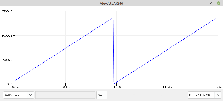
The zigzag graph is transmitted 0 to the maximum possible value of the DAC sector, after which it loops through again. The code for STM32L432 is as follows, and the result is as shown in Figure 4.
#include <Arduino.h>
#include <math.h>

#define pinSpk A3 // PA4
#define pinMic D3 // PB0

#define ADC_BITS 12
#define DAC_BITS 12
#define MAX_VALUE pow(2,DAC_BITS)

int adcValue;

void setup() {
  Serial.begin(115200);
  analogReadResolution(ADC_BITS);
  analogWriteResolution(DAC_BITS);
}

void loop() {
  for (int i = 0; i < MAX_VALUE; i += 16) {
    analogWrite( pinSpk, i);
    adcValue = analogRead(pinMic);
    Serial.println(adcValue);
  }
}
Triangular graph
The triangular graph works similarly to the zigzag principle with the addition of a loop to return the maximum value to 0 as in the following STM32L432 code, and the resulting example is shown in Figure 5.
#include <Arduino.h>
#include <math.h>

#define pinSpk A3 // PA4
#define pinMic D3 // PB0

#define ADC_BITS 12
#define DAC_BITS 12
#define MAX_VALUE pow(2,DAC_BITS)

int adcValue;

void setup() {
  Serial.begin(115200);
  analogReadResolution(ADC_BITS);
  analogWriteResolution(DAC_BITS);
}

void loop() {
  for (int i = 0; i < MAX_VALUE; i += 32) {
    analogWrite( pinSpk, i);
    adcValue = analogRead(pinMic);
    Serial.println(adcValue);
  }
  for (int i = MAX_VALUE-1; i >= 0; i -= 32) {
    analogWrite( pinSpk, i);
    adcValue = analogRead(pinMic);
    Serial.println(adcValue);
  }
}
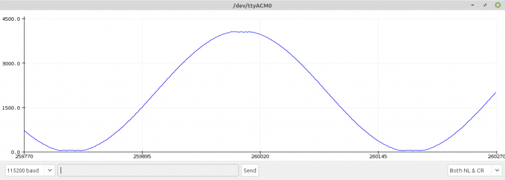
Sing wave graph
Constructing a sinusoidal wave graph uses a loop designation to increase the degree angle from 0 to 359, with each cycle doing the following:
- Convert degrees to radians
- Calculate the sine from the radian angle.
- Converts decimal values to integers in the value range supported by the DAC.
- Read the value from the ADC.
- Send data through serial port to program Serial Plotter.
The code for the STM32L432 is as follows, and the example output is shown in Figure 6.
#include <Arduino.h>
#include <math.h>

#define pinSpk A3 // PA4
#define pinMic D3 // PB0

#define ADC_BITS 12
#define DAC_BITS 12
#define MAX_VALUE pow(2,DAC_BITS)

int adcValue;

void setup() {
  Serial.begin(115200);
  analogReadResolution(ADC_BITS);
  analogWriteResolution(DAC_BITS);
}

void loop() {
  int degree = 0;
  float radian = 0.0;
  float sineValue = 0.0;
  int dValue = 0;
  for (degree = 0; degree < 360; degree++) {
    radian = (float)degree * (2.0 * 3.1415926) / 360.0;
    sineValue = sin(radian);
    dValue = (int)((1.0 + sineValue) * ((MAX_VALUE/2)-1));
    analogWrite( pinSpk, dValue );
    adcValue = analogRead(pinMic);
    Serial.println(adcValue);
  }
}
Conclusion
From this article, we have found that the STM32L432’s ADC has 1 channel, but also has 2 more channels of the DAC with a resolution of 12 bits, making it suitable for processing or generating sound for higher resolution left and right speakers than any other microcontroller we’ve written before. Finally, have fun with programming.
(C) 2020-2022, By Jarut Busarathid and Danai Jedsadathitikul
Updated 2022-01-27