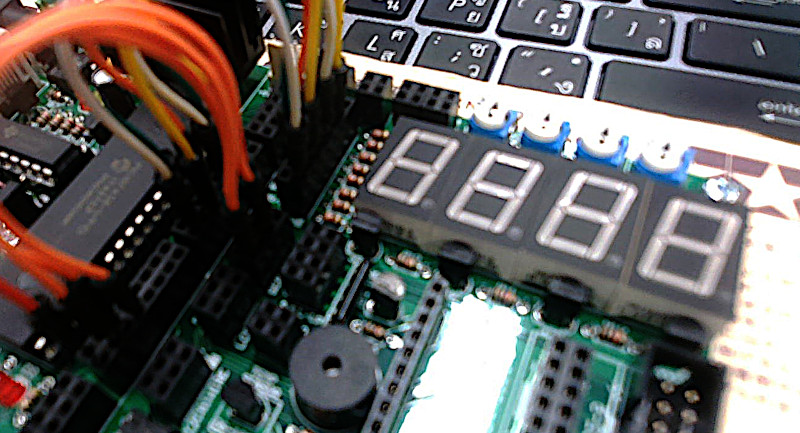
This article is the application of GPIO of PIC18F458 to operate the circuit of 8 LEDs arranged in the same position as the numbers shown in Figure 1 by using 8 LED to be rearranged and called 7-Segment that can be applied to display numbers and another number of characters. In addition, the experimental board has installed a 7-Segment of 4 digits, allowing you to write a program to control the display of 4 digits of data.
7-Segment
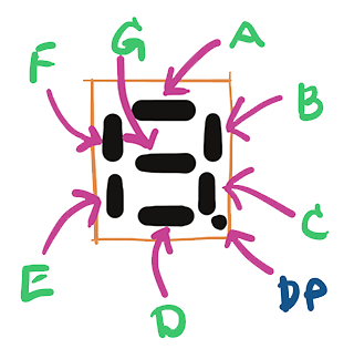
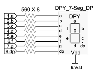
7-Segment has a total of 8 LEDs for different parts called A, B, C, D, E, F, G and DP as shown in Figure 2 and the circuit connection of each digit module is as shown in the diagram in Figure 3.
From http://www.etteam.com/article/duino_stm32_ex01/part5.html
From http://www.etteam.com/article/duino_stm32_ex01/part5.html
From Figure 3, it can be seen that the common pin is Vdd, which is a pin that accepts DC voltage, that means for the LED to be installed, it must be complete, with power going through the load and grounding the load before it will work or turn on. If we give the pin connected to LED A pull DP to 0 means change the state at the port to ground. Electricity can flow through the load, so the LED is lit and vice versa. If we assign the pin of the port to have a state of 1, which is the same power. It also has no ground, the load is not working, or the LED is not on.
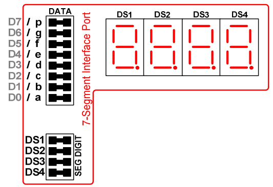
The connection circuit of the 7-Segment Module of the course test board is as shown in Figure 4.
From PCK-1000 guideline
Commanding
From Figure 4, it can be seen that to send to each LED A, B, C, D, E, F, G and P (or DP) must be connected to connectors D0, D1, D2, D3, D4, D5, D6 and D7 by sending values as follows.
- Send 1 means you want the LED to turn on.
- Send 0 means you want the LED to turn off.
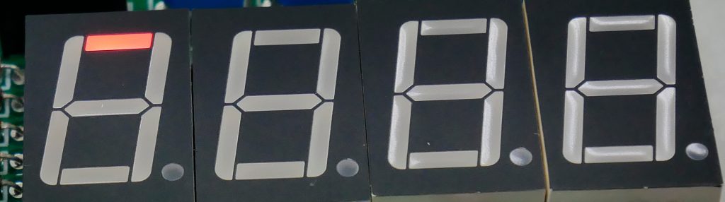
When sending 1 to D0 with the other pin being 0, resulting in the display as shown in Figure 5.
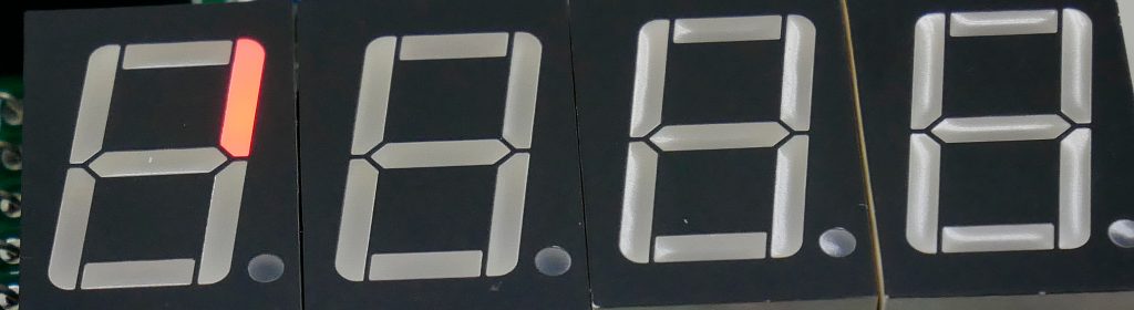
When sending 1 to D1 with the other pin is 0, the result in the display is shown in Figure 6.
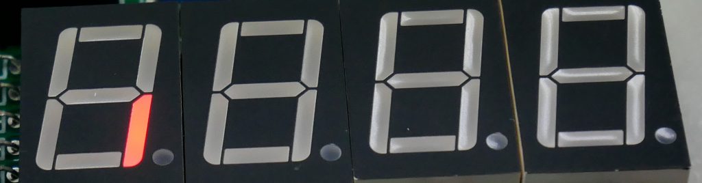
When sending 1 to D2 with the other pin being 0, the result in the display is shown in Figure 7.
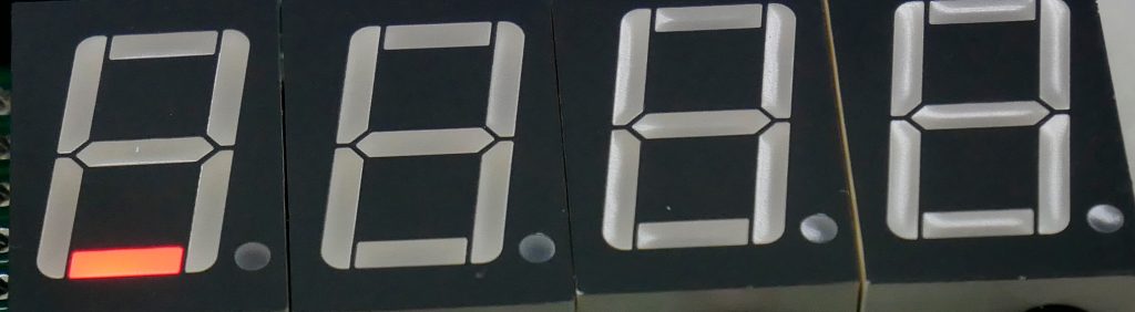
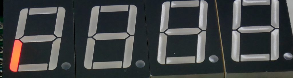
When sending 1 to D3 with the other pin is 0, the result in the display is shown in Figure 8.
When sending 1 to D4 with the other pin being 0, the result in the display is shown in Figure 9.
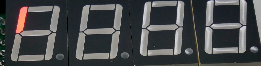
When sending 1 to D5 with the other pin being 0, the result is displayed as shown in Figure 10.
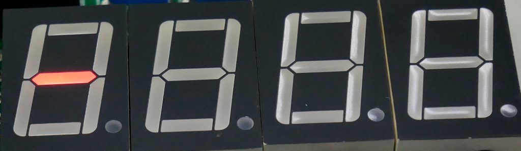
When sending 1 to D6 with the other pin is 0, the result in the display is shown in Figure 11.
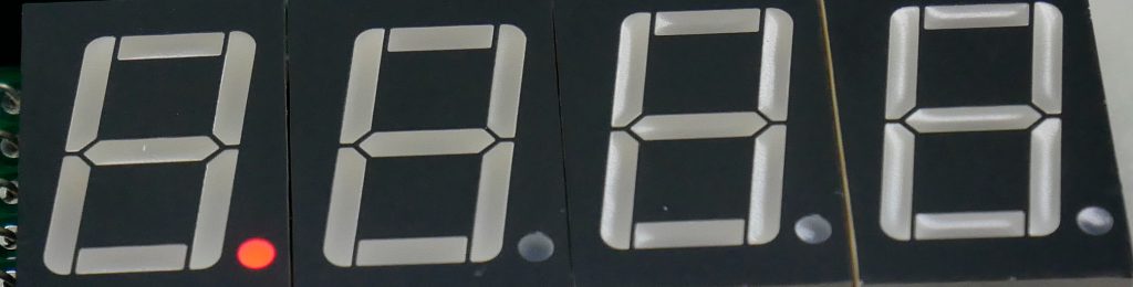
When sending 1 to D7 with the other pin is 0, the result in the display is shown in Figure 12.
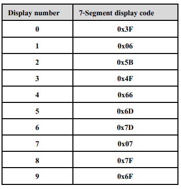
If you want to display it as a number D0, D1, D2, D3, D4, D5, D6 and D7 can be set as shown in the table in Figure 13.
From PCK-1000 Guidebook
In the case of multiple digits
From Figure 4, it can be seen that choosing which digit to attach is determined by giving DS1, DS2, DS3 or DS4 the value of 1. Therefore, if wanting to display 0 on digits 1 and 3, the value of D0, D1, D2, D3, D4, D5, D6, D7, DS1, DS2, DS3 and DS4 must be set as follows:
- D0 is 1
- D1 is 1
- D2 is 1
- D3 is 1
- D4 is 1
- D5 is 1
- D6 is 0
- D7 is 0
- DS1 is 1
- DS2 is 0
- DS3 is 1
- DS4 is 0
Therefore, it was concluded that
- Which LED do you want to be on (lit), set the value to 1.
- If you want any LED to turn off, set the value to 0.
- If you want any digit to be displayed, set the value of that digit to 1.
- If you want any digit to be displayed, set the value of that digit to 1.
Example Code
Example program for using 7-Segment consists of 1 digit and 4 digit control, each of which commands the LED lamp to display to loop with the numeric display as follows:
Running the LED
The first example instructs the LED lamps A, B, C, D, E, F, G and DP or P to display one position at a time to test the correctness of the circuit connections and the circuit inside the 7-Segment module whether it works properly or not. Are there any tubes missing or worn out? By connecting the pin of the microcontroller and the 7 Segment circuit is connected as follows
- RC0 connected to D0
- RC1 connected to D1
- RC2 connected to D2
- RC3 connected to D3
- RC4 connected to D4
- RC5 connected to D5
- RC6 connected to D6
- RC7 connected to D7
- RD0 connected to DS1
The working principle of the program consists of two parts:
- setup()
- Set the value of the output port C to 0b00000001 or 0x01 to make the LED position A bright.
- Set the pin of port C to act as outputs.
- Set the pins of Port D to be outputs same as Port C.
- loop()
- Turn off the 1st digit selection of the 7Segment module by setting RD0 to 0.
- Transfer display format data to port C
- Shift the bit of the display pattern to the left by 1 bit.
- If the value caused by the bit shift causes the variable to be 0, set the variable value to 0x01 or 0b00000001 to restart the display at position A.
- Turn on display by setting RD0 to 1.
- Delay time to see the effect of the display.
An example program is as follows. And the example of the work is as shown in clip 1
#pragma config OSC = HS
#pragma config OSCS = ON
#pragma config PWRT = OFF
#pragma config BOR = ON
#pragma config BORV = 25
#pragma config WDT = OFF
#pragma config WDTPS = 128
#pragma config STVR = ON
#pragma config LVP = ON
#pragma config CP0 = OFF
#pragma config CP1 = OFF
#pragma config CP2 = OFF
#pragma config CP3 = OFF
#pragma config CPB = OFF
#pragma config CPD = OFF
#pragma config WRT0 = OFF
#pragma config WRT1 = OFF
#pragma config WRT2 = OFF
#pragma config WRT3 = OFF
#pragma config WRTC = OFF
#pragma config WRTB = OFF
#pragma config WRTD = OFF
#pragma config EBTR0 = OFF
#pragma config EBTR1 = OFF
#pragma config EBTR2 = OFF
#pragma config EBTR3 = OFF
#pragma config EBTRB = OFF

#include <xc.h>

#define _XTAL_FREQ 20000000

unsigned char seg_pattern = 0b00000001;

void setup() {
    TRISC = 0x00; // 0b00000000
    TRISD = 0x00; // 0b00000000
}

void loop() {
    // disable
    PORTD = 0b00000000;
    // transfer
    PORTC = seg_pattern;
    seg_pattern <<= 1;
    if (seg_pattern == 0x00) {
        seg_pattern = 0x01;
    }
    // enable
    PORTD = 0b00000001;
    // delay
    __delay_ms(100);
}

void main(void) {
    setup();
    while (1) {
        loop();
    }
    return;
}Count from 0 to 9
From Figure 13, which is a table of values sent to D0, D1, D2, D3, D4, D5, D6 and D7 to display the numbers 0 to 9 when writing a program, it will be as follows. And the example of the display is according to Video 2.
#pragma config OSC = HS
#pragma config OSCS = ON
#pragma config PWRT = OFF
#pragma config BOR = ON
#pragma config BORV = 25
#pragma config WDT = OFF
#pragma config WDTPS = 128
#pragma config STVR = ON
#pragma config LVP = ON
#pragma config CP0 = OFF
#pragma config CP1 = OFF
#pragma config CP2 = OFF
#pragma config CP3 = OFF
#pragma config CPB = OFF
#pragma config CPD = OFF
#pragma config WRT0 = OFF
#pragma config WRT1 = OFF
#pragma config WRT2 = OFF
#pragma config WRT3 = OFF
#pragma config WRTC = OFF
#pragma config WRTB = OFF
#pragma config WRTD = OFF
#pragma config EBTR0 = OFF
#pragma config EBTR1 = OFF
#pragma config EBTR2 = OFF
#pragma config EBTR3 = OFF
#pragma config EBTRB = OFF

#include <xc.h>

#define _XTAL_FREQ 20000000


unsigned char number_patterns[] = {
    0x3F,
    0x06,
    0x5B,
    0x4F,
    0x66,
    0x6D,
    0x7D,
    0x07,
    0x7F,
    0x6F
};


void setup() {
    TRISC = 0x00; // 0b00000000
    TRISD = 0x00; // 0b00000000
}

void loop() {
    for (int i=0; i<10; i++) {
        // disable
        PORTD = 0b00000000;
        // transfer
        PORTC = number_patterns[i];
        // enable
        PORTD = 0b00000001;
        // delay
        __delay_ms(1000);
    }
}

void main(void) {
    setup();
    while (1) {
        loop();
    }
    return;
}Skipping some number
Example 3 is to set the values of position G of digits 1 to 4, lined up as if jumping back and forth between digits (Video 3) by setting PORTC to 0b01000000 and PORTD as dsx values. The values of 0x01, 0x02, 0x04, and 0x08 are lined up with a bit shifted left each cycle. The program code is as follows.
#pragma config OSC = HS
#pragma config OSCS = ON
#pragma config PWRT = OFF
#pragma config BOR = ON
#pragma config BORV = 25
#pragma config WDT = OFF
#pragma config WDTPS = 128
#pragma config STVR = ON
#pragma config LVP = ON
#pragma config CP0 = OFF
#pragma config CP1 = OFF
#pragma config CP2 = OFF
#pragma config CP3 = OFF
#pragma config CPB = OFF
#pragma config CPD = OFF
#pragma config WRT0 = OFF
#pragma config WRT1 = OFF
#pragma config WRT2 = OFF
#pragma config WRT3 = OFF
#pragma config WRTC = OFF
#pragma config WRTB = OFF
#pragma config WRTD = OFF
#pragma config EBTR0 = OFF
#pragma config EBTR1 = OFF
#pragma config EBTR2 = OFF
#pragma config EBTR3 = OFF
#pragma config EBTRB = OFF

#include <xc.h>

#define _XTAL_FREQ 20000000

unsigned char dsx=0x01;

void setup() {
    TRISC = 0x00; // 0b00000000
    TRISD = 0x00; // 0b00000000
}

void loop() {
    // disable
    PORTD = 0b00000000;
    // transfer
    PORTC = 0b01000000;
    // enable
    PORTD = dsx;
    // move next
    dsx <<= 1;
    if (dsx == 0x10) {
        dsx = 0x01;
    }
    // delay
    __delay_ms(100);
}

void main(void) {
    setup();
    while (1) {
        loop();
    }
    return;
}Displays a 4 digit number
The last example shows the numbers of all 4 digits. The function is divided as follows.
- Set all position to 0
- Displays 4th position with 0 to 9
- Displays 3rd position with 0 to 9
- Displays 2nd position with 0 to 9
- Displays 1st position with 0 to 9
The program code is as follows and a sample Video of the work as shown in Video 4.
#pragma config OSC = HS
#pragma config OSCS = ON
#pragma config PWRT = OFF
#pragma config BOR = ON
#pragma config BORV = 25
#pragma config WDT = OFF
#pragma config WDTPS = 128
#pragma config STVR = ON
#pragma config LVP = ON
#pragma config CP0 = OFF
#pragma config CP1 = OFF
#pragma config CP2 = OFF
#pragma config CP3 = OFF
#pragma config CPB = OFF
#pragma config CPD = OFF
#pragma config WRT0 = OFF
#pragma config WRT1 = OFF
#pragma config WRT2 = OFF
#pragma config WRT3 = OFF
#pragma config WRTC = OFF
#pragma config WRTB = OFF
#pragma config WRTD = OFF
#pragma config EBTR0 = OFF
#pragma config EBTR1 = OFF
#pragma config EBTR2 = OFF
#pragma config EBTR3 = OFF
#pragma config EBTRB = OFF

#include <xc.h>

#define _XTAL_FREQ 20000000

unsigned char number_patterns[] = {
    0x3F,
    0x06,
    0x5B,
    0x4F,
    0x66,
    0x6D,
    0x7D,
    0x07,
    0x7F,
    0x6F
};

void setup() {
    TRISC = 0x00; // 0b00000000
    TRISD = 0x00; // 0b00000000
}

void loop() {
    int idx=0;
    /////////////////// step 1 ////////////////////////
    // disable
    PORTD = 0b00000000;
    // transfer
    PORTC = number_patterns[0];
    // enable
    PORTD = 0b00001111;
    /////////////////// step 2 ////////////////////////
    for (idx=0; idx<10; idx++) {
        for (int counter=0; counter<10; counter++) {
            // disable
            PORTD = 0b00000000;
            // transfer
            PORTC = number_patterns[0];
            // enable
            PORTD = 0b0000111;
            __delay_ms(10);
            // transfer
            PORTC = number_patterns[idx];
            // enable
            PORTD = 0b0001000;
            // delay
            __delay_ms(10);
        }
    }
    /////////////////// step 3 ////////////////////////
    for (idx=0; idx<10; idx++) {
        for (int counter=0; counter<10; counter++) {
            // disable
            PORTD = 0b00000000;
            // transfer
            PORTC = number_patterns[0];
            // enable
            PORTD = 0b0001011;
            __delay_ms(10);
            // transfer
            PORTC = number_patterns[idx];
            // enable
            PORTD = 0b0000100;
            // delay
            __delay_ms(10);
        }
    }
    /////////////////// step 4 ////////////////////////
    for (idx=0; idx<10; idx++) {
        for (int counter=0; counter<10; counter++) {
            // disable
            PORTD = 0b00000000;
            // transfer
            PORTC = number_patterns[0];
            // enable
            PORTD = 0b0001101;
            __delay_ms(10);
            // transfer
            PORTC = number_patterns[idx];
            // enable
            PORTD = 0b0000010;
            // delay
            __delay_ms(10);
        }
    }
    /////////////////// step 5 ////////////////////////
    for (idx=0; idx<10; idx++) {
        for (int counter=0; counter<10; counter++) {
            // disable
            PORTD = 0b00000000;
            // transfer
            PORTC = number_patterns[0];
            // enable
            PORTD = 0b0001110;
            __delay_ms(10);
            // transfer
            PORTC = number_patterns[idx];
            // enable
            PORTD = 0b0000001;
            // delay
            __delay_ms(10);
        }
    }
}

void main(void) {
    setup();
    while (1) {
        loop();
    }
    return;
}
From the program code, it is found that the counter loop is repeated 10 times, resulting in the human eye seeing the number clearly. This is because the display shows the value of 0 of 3 digits for 20 milliseconds, and the numeric value that cycles through the idx for another 20 milliseconds, for a total display time of 40 milliseconds per cycle (for students to try to change this value, or omit it, and increase the number of revolutions of the counter to observe the change and save the results for further use experience)
Conclusion
From this article, the reader has learned how to control a 7-segment module in both single-digit and multi-digit. It will be found that the working principle is the same as sending data 0 or 1 to the pin of the microcontroller. But with a suitable method for the circuit, the display will change differently. Therefore, programming must have an understanding of the working principle of that circuit. Therefore, it will be able to order the work as desired. And more importantly, to think about how it will produce results and whether it can be done or not, it takes some experience and experimentation before you can judge whether the concept that has been created is true. How can this be done? Or it can’t be done for whatever reason. Finally, have fun with programming.
(C) 2022, By Anuchart Boonmark, Jarut Busarathid and Danai Jedsadathitikul
Updated 2022-03-24