In this article, we will learn about GPIO (General Purpose I/O) or pin connect to an external device of microcontroller with C++ of Arduino using esp8266 as reference chip. This can be applied to Arduino Uno, Arduino Mega or STM32 as well. Under this article, we describe the duty of the pin, output and the input signal.

From Figure 1, it can be seen that the pins of the esp8266 have different names. Each pin has a different function as well. The functions of the pins are as follows:
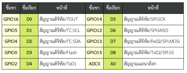
From this table, it can be found that the pins that can be used without affecting the operation of the esp8266 are D1, D2, D4, D5, D6, D7 and A0. A0 can only input analog signals up to 3.3VDC voltage (actually 1VDC, but the board has a voltage attenuation circuit).
Pins setting
The format of the commands to be defined in the setup() function is as follows.
pinMode( pin, duty )
where
pin is name of the pin
function is a constant INPUT to input data from a given pin or OUTPUT to output data to a given pin.
An example of setting GPIO4 to be a digital signal input and GPIO5 to be a digital signal output can be coded as follows
void setup( ) {
	pinMode( 4, INPUT );
	pinMode( 5, OUTPUT );
}
Digital signal output
Digital signal output is an instruction that the pin of the microcontroller port has a logic state of LOW or HIGH, which affects the transmission of voltage at the analog signal level. Sending LOW is like adjusting the pin of the microcontroller port to be the ground of the electrical circuit and HIGH is the pin of the microcontroller port as a source of 3.3V DC voltage and can drive a load not more than the limit. The digital output pin must be assigned an OUTPUT function with the pinMode( ) command before performing a digital output. The format of the digital output command is as follows.
digitalWrite( pin, digital_signal )
where
Pin is the pin number that has been assigned the function of OUTPUT.
The Digital signal level is the digital signal level to be output. There are 2 types, HIGH and LOW for digital signal voltage 1 and 0 respectively.
An example of signaling a digital signal at Pin 4 to be LOW and Pin 5 to be HIGH. You can write command as follows.
pinMode( 4, OUTPUT );
pinMode( 5, OUTPUT );
digitalWrite( 4, LOW );
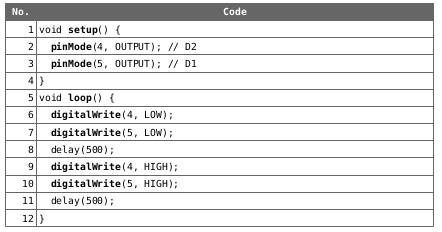
digitalWrite( 5, HIGH );Example program for ordering LED to glow or turn it off. In this experiment, it is used with the ET-TEST 10P/OUT device as shown in Figure 2, the code is as follows:


Digital signal import
The digital signal input from the microcontroller’s port must always be assigned to the pin as the INPUT pin in the setup( ) function or change the state with pinMode( ) before the digital signal is imported. The format of the command to import digital signals to be stored in the variable “result” from the port “PIN” can be written as follows:
result = digitalRead( pin )
where
result is a digital signal voltage output variable which is HIGH or LOW for representing the digital signal voltage 1 and 0, respectively.
pin is a pin number assigned to act as digital signal input.
An example of importing digital signals from pin 16 or D0 and storing them in variable d0_stat can be written as the following command:
pinMode( 16, INPUT );
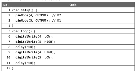
int d0_stat = digitalRead( 16 );An example program for importing digital signals from Board ET-TEST 10P/INP and sending it to ET-TEST 10P/OUT as shown in Figure 3 has the following code:


Analog signal reception
Converting an analog signal which is a continuous signal from the input signal to a discrete signal called digital in the form of a digital number. The steps of converting analog signals to digital signals are:
- When an analog signal is sent to the converter called ADC
- The converter compares the voltage to a digital integer value.
- The converter returns the converted data to a digital numerical value.
Instructions for reading analog signal data that read the analog-to-digital conversion result and store it in vDigital variables are of the following format:
vDigital = analogRead( 0 )
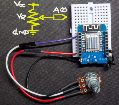
An example of reading from the voltage obtained from the adjustable resistor as shown in Figure 4 is as follows.

Some other interesting analog signal statements are as follows.
- analogReadResolution( bits ) is used to determine the number of bits of sampling (usually based on the microcontroller, for example, esp32 is 12 bits).
- analogSetWidth( width ) used to set the width of the read value. For example, an 8-bit ADC will have 256 values, or 0 to 255, a 10-bit ADC will have 1024 values, or 0 to 1023, etc.
- analogSetCycles( cycle ) defines the number of cycles per sample, which normal value is 8 from values in the range 1 to 255.
- analogSetClockDiv( divider ) determine the divisor for the ADC circuit, usually 1, from values in the range 1 to 255.
- analogSetAttenuation( attenuation ) for implementations with esp32, the attenuation reservation yields the following, usually ADC_0db, or no attenuation.
- ADC_0db set without attenuation, the ADC can measure up to approximately 800 mV (1V input = 1088 ADC reading).
- ADC_2_5db the ADC input voltage is attenuated, extending the measurement range up to approximately 1100 mV (1V input = 3722 ADC reading).
- ADC_6db the ADC input voltage is attenuated, extending the measurement range up to approximately 1350 mV (1V input = 3033 ADC reading).
- ADC_11db The ADC input voltage is attenuated, extending the measurement range up to approximately 2600 mV (1V input = 1575 ADC reading).
- analogSetPinAttuation( pin, attenuation ) Set the attenuation input from the pin by default attenuation to ADC_11db.
- con = adcAttchPin( pin ) Connect the pin to the ADC, if successful, return TRUE, if failed, return FALSE.
- adcStart( pin ) Instructs the ADC of the pin to start.
- status = adcBusy( pin ) Check pin status, if return TRUE, ADC is empty, if FALSE, ADC is working.
- resultadcEnd( pin ) Read the conversion value from the ADC of the pin.
Conclusion
From this article, you will find that the process of using GPIO has the first step that must be done is to define the functions of the pin and to take out the digital signal, use the command digitalWrite(). To import a digital signal, use the command digitalRead() and if you want to import an analog signal, use analogRead() command. Finally, have fun with programming.
(C) 2020-2021, By Jarut Busarathid and Danai Jedsadathitikul
Updated 2021-11-11