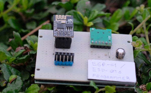
This article introduces the esp8266 module named ESP-01s with 8 pin connectors, explaining the functions of each pin. Expansion of the circuit to program the chip (Example shown in Figure 1). Making the chip work and including an example of programming to use this module with Arduino to give an overview of the development of the system, which is a system that is attractively priced.
Features
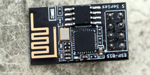
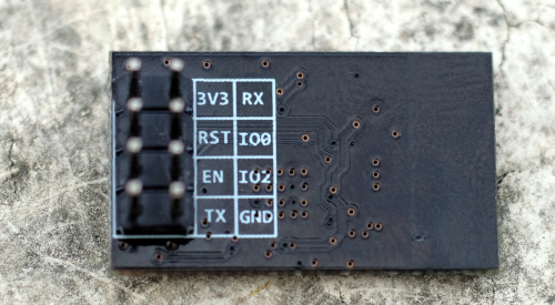
The ESP-01 and ESP-01s are small modules as shown in Figures 2 and 3 that are designed to focus on wireless networking to other microcontrollers via RS232 with AT commands RX/TX/CH_PD/Vcc and GND so it can be programmed into chip ESP8266 by setting pin GPIO0 to GND at system boot, making this module more versatile.
The features of the ESP-01 and ESP-01s are as follows.
- Tensilica L106 processor is a 32-bit processor.
- Clock frequency 160MHz.
- Less than 50KB of SRAM is available because it must be used in conjunction with a communication buffer.
- The ROM of ESP-01 is 512KB and ESP-01s is 1MB.
- Operating voltage 2.5V to 3.6v.
- Temperature -40 to 125 degrees Celsius.
- Normal operating current requirement is about 80mA.
- Current requirement in Power Saving Mode (Sleep Mode) 20uA
- Supports IEEE 802.11 b/g/n standards.
- Supports WPA/WPA2
- Supports WEP/TKIP and AES
- Supports IPv4, TCP/UDP/HTTP
- Pins
- RX
- TX
- GPIO0
- GPIO2
The function diagram of the ESP8266 is shown in Figure 4.
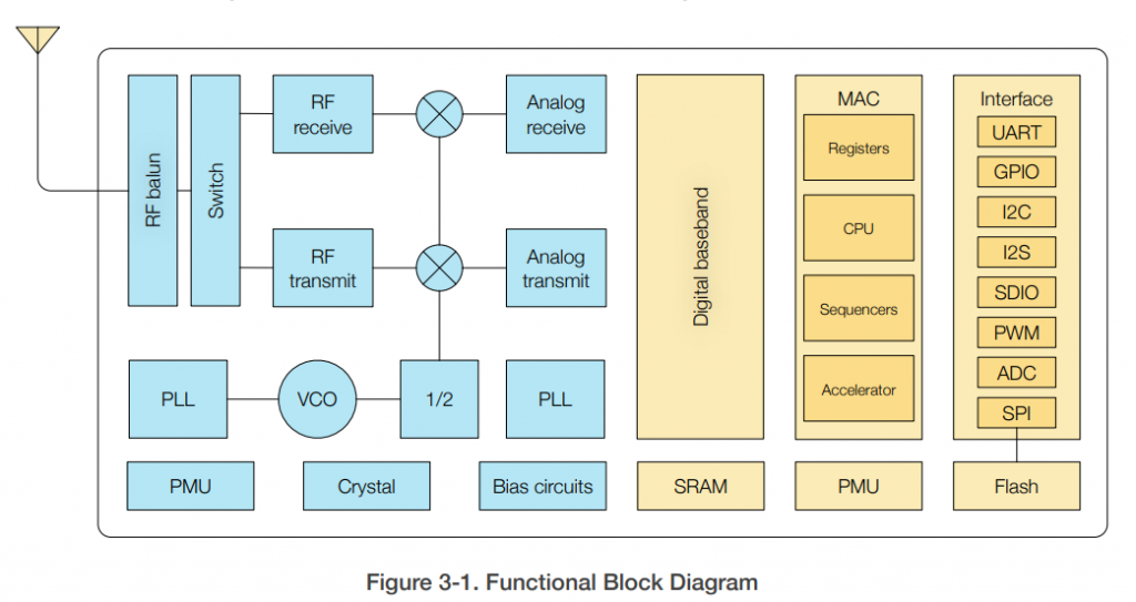
FROM page 12 Figure 3-1
Functional design
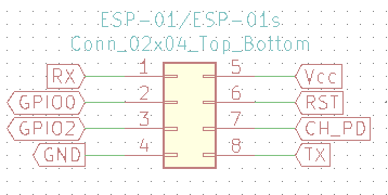
From the 8 pins of the ESP-01/ESP-01s module in Figure 5, it can be seen that the module supports 2 GPIO pins, 2 and 0.
- It is used to set the operation when the system starts, that is, if the status is GND, it means to enter the chip program mode, and if it is 1, it means it works normally.
- It is connected to an LED circuit on the module for displaying the working status.
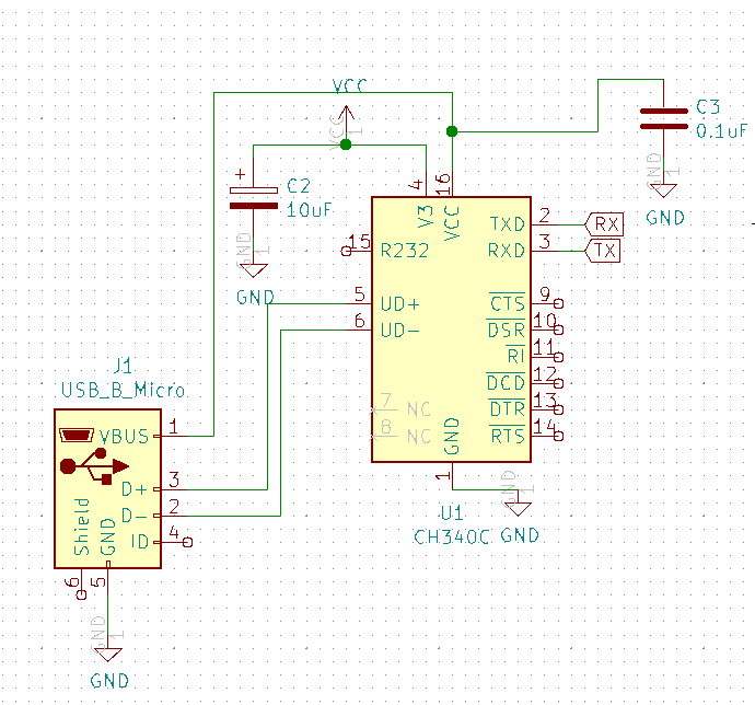
From Pin TX and RX used to connect to serial communication module by connecting as shown in Figure 6.
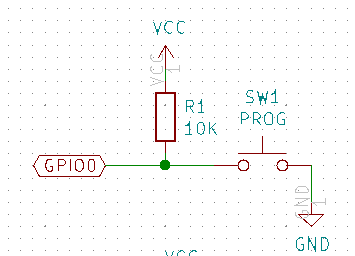
Making circuit supports the selection of operating modes of ESP-01/ESP-01s Can be done as shown in Figure 7, in normal conditions, when SW1 is not pressed, pin GPIO0 has status as 1, so it works in normal working mode, but if SW1 is pressed, pin GPIO0 has a status of 0 and when restarting the system, it will enter the ESP8266 chip program mode.
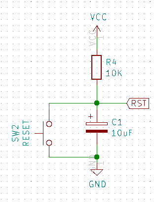
The RST pin of the ESP-01/ESP-01s module was designed to allow users to reset the operation of the module in case the system freezes or fails. The circuit for resetting with SW2 is as shown in Figure 8.
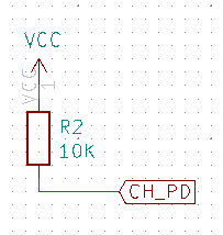
The CH_PD pin is the module’s En pin and is used to enable or disable the module. Usually connected to Vcc as shown in Figure 9.
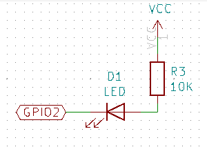
LED sector on module ESP-01/ESP-01s are connected to pin GPIO2 as shown in Figure 10, it is found that ordering the LED to light up must send signal 0 to complete the circuit and ordered to be turned off by sending 1.
From the circuit that is added, it is found that it is less complicated and can be used easily. The next step is to experiment with programming.
Coding
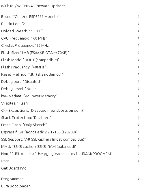
Setting up the ESP-01s, choose to use the Board as Generic ESP8266 Module by setting the CPU Frequency to 160MHz or want to reduce it to 80MHz as well to save energy and doesn’t need highly processing power. The important thing of setting is Flash Size, choose 1MB (FS:64KB OTA:~470KB) as shown in Figure 11.
An example of an LED driver at pin GPIO02 is as follows. For other programs, see the example of using WiFi classes in the previous article.
#define ledPin 2
void setup() {
pinMode( ledPin, OUTPUT );
}
void loop() {
digitalWrite( ledPin, HIGH );
delay(1000);
digitalWrite( ledPin, LOW );
delay(1000);
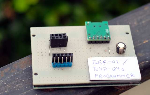
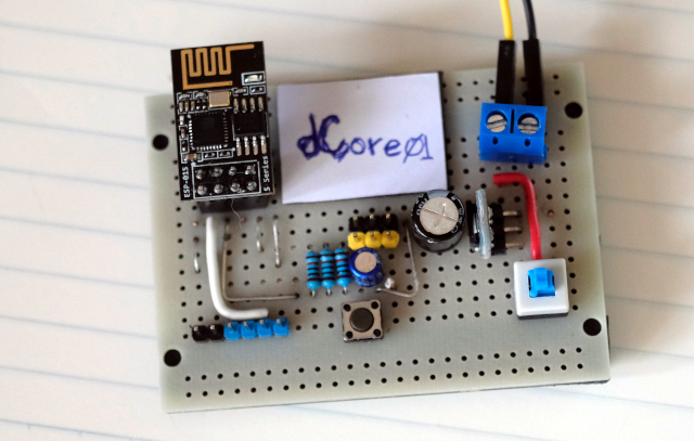
}For the convenience and economy of the development system we choose to make a board for programming the chip as shown in Figure 12 and the board for using the module as shown in Figure 13 because usually we do not use the UART sector but focus on acting as an AP or Server, so it can reports on site which can be viewed from a web browser.
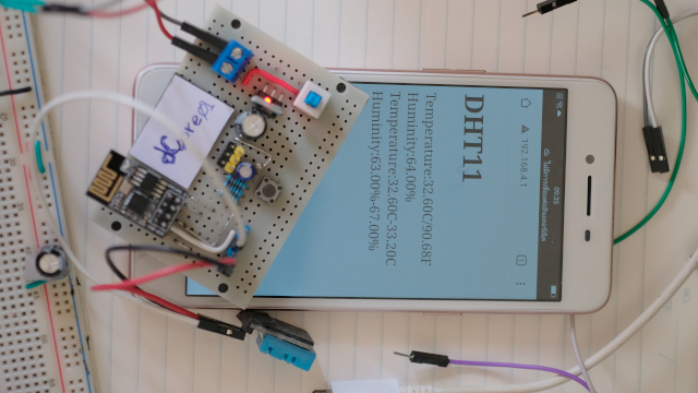
The next example uses DHT11 as a temperature and humidity sensor connected to the ESP-01s via GPIO2 and reported via a SoftAP web browser. The sample results are shown in Figure 14.
#include <DHT.h>
#include <ESP8266WiFi.h>

#define AP_NAME "AP"
#define AP_PASSWD "password"
IPAddress myIP(192, 168, 4, 1);
IPAddress gwIP(192, 168, 4, 10);
IPAddress subnet(255, 255, 255, 0);

DHT dht = DHT(2, DHT11);
WiFiServer server(80);

float minC = 100.0f, maxC = 0.0f; // min max temp c
float minH = 100.0f, maxH = 0.0f; // min max temp f
float hic; // headt index C
float hif;// headt index  F
float h; // humidity
float tc; // temp in C
float tf; // temp in F

void getDHT11() {
  h = dht.readHumidity();
  tc = dht.readTemperature();
  tf = dht.readTemperature(true);

  if (isnan(h) || isnan(tc) || isnan(tf)) {
    h = -1.0f;
    tc = -1.0f;
    tf = -1.0f;
    hic = -1.0f;
    hif = -1.0f;
    return;
  }

  hic = dht.computeHeatIndex(tc, h, false);
  hif = dht.computeHeatIndex(tf, h);

  if (minC > tc) {
    minC = tc;
  }
  if (maxC < tc) {
    maxC = tc;
  }
  if (minH > h) {
    minH = h;
  }
  if (maxH < h) {
    maxH = h;
  }
}

void setup() {
  Serial.begin(115200);
  Serial.println("\n\n\n");
  dht.begin();
  if (WiFi.softAPConfig( myIP, gwIP, subnet )) {
    if (WiFi.softAP(AP_NAME, AP_PASSWD, 8, false, 5)) {
      Serial.print("IP Address : ");
      Serial.println(WiFi.softAPIP());
    } else {
      Serial.println("softAP() failed!!");
      while (true);
    }
  } else {
    Serial.println("softAPConfig() failed!");
    while (true);
  }
  server.begin();
}

String htmlPage() {
  String html;
  getDHT11();
  html.reserve(2048);               // prevent ram fragmentation
  html = F("HTTP/1.1 200 OK\r\n"
           "Content-Type: text/html\r\n"
           "Connection: close\r\n"  // the connection will be closed after completion of the response
           "Refresh: 5\r\n"         // refresh the page automatically every 5 sec
           "\r\n"
           "<!DOCTYPE HTML>"
           "<html><head></head><body>"
           "<h1>DHT11</h1>");
  html += F("<div>Temperature:");
  html += tc;
  html += F("C/");
  html += tf;
  html += F("F</div>");
  html += F("<div>Huminity:");
  html += h;
  html += F("%</div>");
  html += F("<div>Temperature:");
  html += minC;
  html += F("C-");
  html += maxC;
  html += F("C</div>");
  html += F("<div>Huminity:");
  html += minH;
  html += F("%-");
  html += maxH;
  html += F("%</div>");
  html += F("</body></html>\r\n");
  return html;
}

void loop() {
  WiFiClient client = server.available();

  if (client)   {
    Serial.println("\n[Client connected]");
    while (client.connected()) {
      if (client.available()) {
        String req = client.readStringUntil('\r');
        Serial.print(req);
        if (req.indexOf("GET / HTTP/1.1")) {
          client.println(htmlPage());
          break;
        }
      }
    }

    while (client.available()) {
      client.read();
    }

    client.stop();
    Serial.println("[Client disconnected]");
  }
}
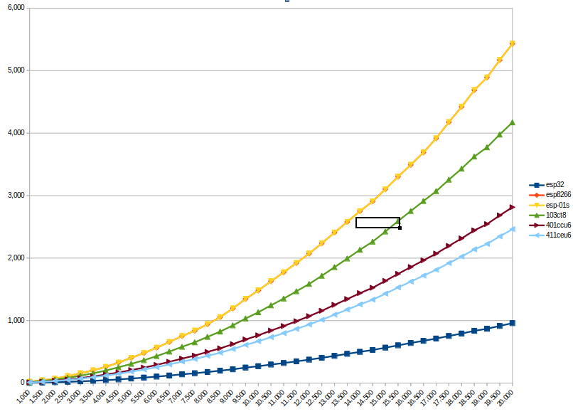
And when our team has tested and run to find prime numbers from numbers 1000, 1500, 2000, 2500, 3000, 3500, 4000, 4500, .., 19500, 20000, it was found that the speed is the same as the general NodeMCU board as shown in Figure 15.
Conclusion
From this article, the esp8266 microcontroller, when miniaturized to focus on wireless networking connectors or ESP-01 modules or ESP-01s, is a relatively inexpensive system. And it works with the same speed as a regular ESP8266 board, but with a more limited GPIO, so the choice depends on the system and the need. Finally, have fun with programming.
If you want to talk with us, feel free to leave comments below!!
References
- ESPRESSIF : ESP8266 Series of Modules
- ESPRESSIF : ESP8266EX DataSheet
(C) 2020-2021, By Jarut Busarathid and Danai Jedsadathitikul
Updated 2021-11-12