This article is an introduction to Cytron’s Maker Pi PICO Board (Figure 1) equipped with a Raspberry Pi PICO microcontroller, as well as an expansion board with the basic equipment needed to practice programming and use, such as tubes, LED, memory card reader (micro SD-Card) or speakers, etc. In addition to the introduction of the board, this article discusses the installation and use CircuitPython which is Python that has adapted MicroPython for use with Adafruit and other third-party devices. For those interested in articles on MicroPython, we recommend consulting Dr. Rawat Siriphokaphirom’s website which has much more complete details than ours.
- MicroPython for RP2040 Pico
- RPi Pico RP2040 Code Examples
- PIO Programming
- PIO Signaling and Measurement
- There is also a section CircuitPython in the article CircuitPython for Pico RP2040
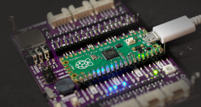
Maker Pi PICO
Cytron’s Maker Pi PICO board consists of 2 parts:
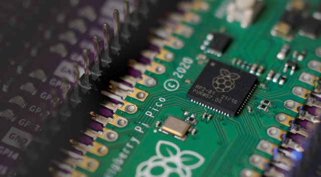
- Raspberry Pi Pico microcontroller board (as shown in Figure 2)
- Raspberry Pi Pico Microcontroller Port Expansion Board.
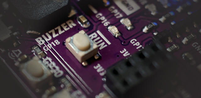
On the expansion board, there is a RUN switch as shown in Figure 3 for pressing when wanting to start a new program or perform a system reset. This is useful when you want to upload the program to the board. Usually, the cable must be unplugged and plugged in again but with this button, you can press and hold the BOOT0 button on the microcontroller board and then press the RUN button to start working again into the chip programming mode.
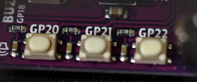
In addition to the RUN switch, some switches can be used by connecting GP20, GP21 and GP22 as shown in Figure 4. Each button is Active Low due to the Pull-up circuit connected.
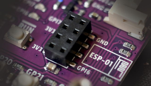
The part that we like the most is that there is a connector for ESP-01 on board as shown in Figure 5 which communicates via UART2 with pins GP17 and GP16.
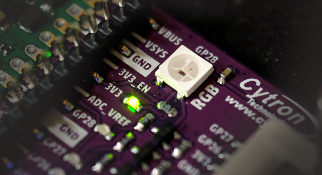
The next part is without RGB LED that is connected to pin GP28 as shown in Figure 6, enabling you to write a program to turn on or off the LED. You can configure the color of the display.
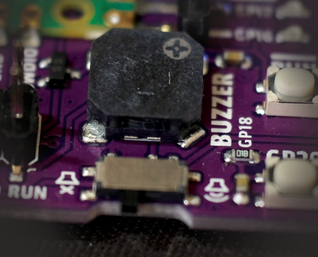
The bottom of the board has a buzzer speaker with a switch to turn on / off the speaker as shown in Figure 7, connected to the GP18
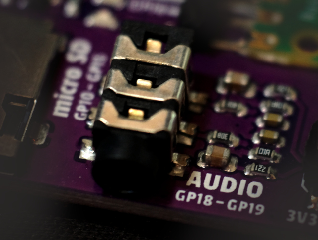
Stereo headphone jack as shown in Figure 8 connected to GP18 and GP19 pins.
Finally, there is a micro SD reader that is already installed as shown in Figure 9, which is connected via the SPI bus with pins GP10, GP11, GP12, GP13, GP14 and GP15, as follows:
- GP10 is SCK1 for sending clock signals to communicate with each other.
- GP11 is SDO1 or CMD for sending data
- GP12 is SDI1 or DAT0 for receiving input
- GP13 is DAT1
- GP14 is DAT2
- GP15 is CSn1 or CD/DAT3 for the CS pin to start or end the communication.

Install CircuitPython
CircuitPython was developed from MicroPython that can be downloaded from the CircuitPython main page which will be displayed as shown in Figure 10.
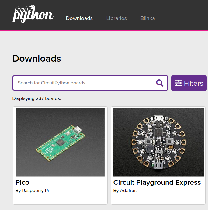
From the main page, click on the Downloads option to access the program download page as shown in Figure 11.
From Figure 11, you can see that on this page there is a list of boards to choose, if you don’t want to scroll to find the board you want, you can type the name of the active board and the system will search. If found means that the board can be used with CircuitPython, in this case, select the Pico board.
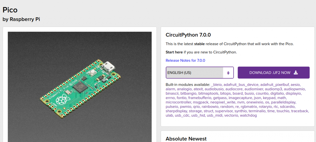
When you click on the Pico By Raspberry Pi page, there will be a list of models of CircuitPython to download. By the time the author accesses version 7.0.0, click Download to download the UF2 file as shown in Figure 11.
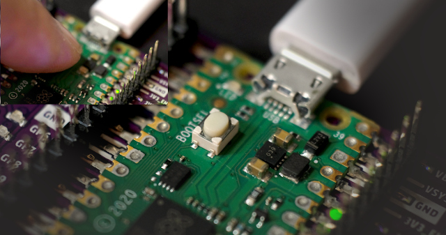
Once downloaded is completed, reboot into the chip program mode. By pressing the BOOTSEL button in Figure 12, then press Run, then release the RUN button, followed by the BOOTSEL button.
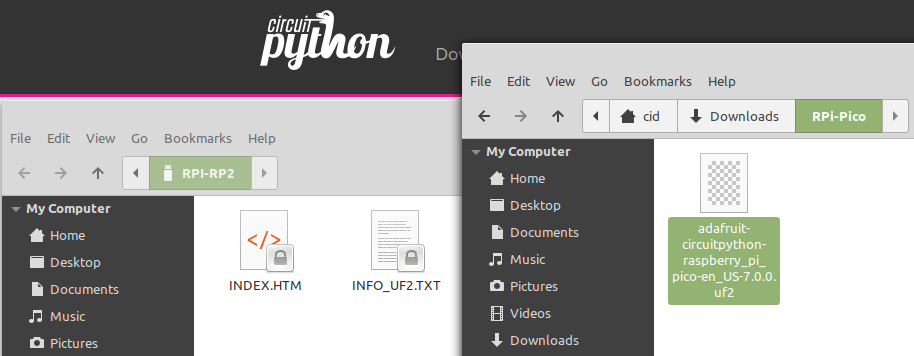
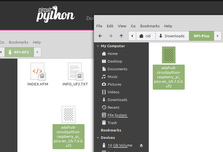
When entering chip program mode, the system will display the folder RPI-RP2 as shown in Figure 13, drag the downloaded file to the folder as shown in Figure 14 to send the file to the microcontroller to program itselft.
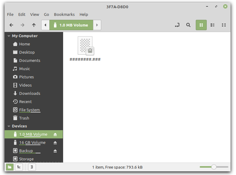
When finished dragging and the chip is successfully programmed, it will be switched to run mode. The program will show a folder for storing data with approximately 1.0MB of space to store programs or data as shown in Figure 14.
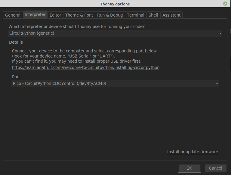
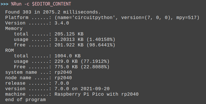
The next step is to use thonny to write a program to find a prime number and read information about the board to display. In the thonny select CircuitPython (generic) and select the correct communication port. Usually, the communication port of the board is named Pico – CircuitPython.CDC control as shown in Figure 15.
The sample program code is as follows and the result is as shown in Figure 16
##################################################################################
# coreInfo
# esp8266/esp32/rp2/stm32f4/stm32f7/micro:bit information
##################################################################################
import gc
import os
import sys
import time

##################################################################################
# system setting
##################################################################################
gc.enable()
gc.collect()

##################################################################################
# function
##################################################################################
def isPrime(x):
    i = 2
    while (i < x):
        if x%i == 0:
            return False
        i = i+1
    if (i == x):
        return True
    return False

def testPrimeNumber(maxN):
    counter = 0
    t0 = time.monotonic_ns()
    for n in range(2, maxN):
        if isPrime(n):
            counter+=1
    t1 = time.monotonic_ns()
    print("Found {} in {} milliseconds.".format(counter,abs(t1-t0)/1000000))


def show_hw_info():
    uname = os.uname()
    mem_total = gc.mem_alloc()+gc.mem_free()
    free_percent = "("+str((gc.mem_free())/mem_total*100.0)+"%)"
    alloc_percent = "("+str((gc.mem_alloc())/mem_total*100.0)+"%)"
    stat = os.statvfs('/flash')
    block_size = stat[0]
    total_blocks = stat[2]
    free_blocks  = stat[3]
    rom_total = (total_blocks * block_size)/1024
    rom_free = (free_blocks * block_size)/1024
    rom_usage = (rom_total-rom_free)
    rfree_percent = "("+str(rom_free/rom_total*100.0)+"%)"
    rusage_percent = "("+str(rom_usage/rom_total*100.0)+"%)"
    print("Platform ......:",sys.implementation)
    print("Version .......:",sys.version)
    print("Memory")
    print("   total ......:",mem_total/1024,"KB")
    print("   usage ......:",gc.mem_alloc()/1024,"KB",alloc_percent)
    print("   free .......:",gc.mem_free()/1024,"KB",free_percent)
    print("ROM")
    print("   total ......:", rom_total,"KB" )
    print("   usage ......:", rom_usage,"KB",rfree_percent )
    print("   Free .......:", rom_free,"KB",rusage_percent )
    print("system name ...:",uname.sysname)
    print("node name .....:",uname.nodename)
    print("release .......:",uname.release)
    print("version .......:",uname.version)
    print("machine .......:",uname.machine)

##################################################################################
# main program
##################################################################################
if __name__=='__main__':
    try:
        testPrimeNumber(2000)
        show_hw_info()
    except KeyboardInterrupt:
        pass
    print("end of program")
Conclusion
From this article, you will find that although they are the same Python language, the libraries are different, so you need to learn more about how to use them. However, if you’re primarily self-programming, you can reuse that code without worrying about platform dependency. Like the prime numbers function that we use in our example programs, for example. For more information on I/O applications, see the articles listed above and in the reference section. Finally, have fun with programming.
References
(C) 2020-2021, By Jarut Busarathid and Danai Jedsadathitikul
Updated 2021-12-13