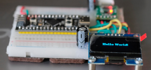
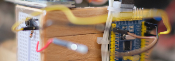
From the article on using the ESP8266 with an OLED graphical display written in Python, you’ll find that it’s fast and easy but when used with other microcontrollers that cannot use Micropython or CircuitPython, what must be done? One of the many options is the u8glib or u8g2 (Universal 8 bit Graphics Library) libraries, designed to work with monochromatic 8-bit graphics over either I2C or SPI communication. In this article, we are using I2C OLED as shown in Figure 1.
This article discusses the SPI bus functionality of the Arduino framework for use with the STM32F030F4P6, STM32F103C8, STM32F401, esp8266 and esp32. The operation of this bus requires at least 3 intercommunication cables: SCLK, MISO. and MOSI for transmitting the clock signal between the sender and the receiver. It serves to receive information from the sender. and used for sending information to the recipient.
From the use of 3 signal lines, it is found that data can be transmitted and received simultaneously. This is different from I2C bus communication that uses only one SDA cable to communicate. At the same communication speed, the SPI bus will receive and transmit data without waiting for an idle line, while I2C will have to wait for idle. With this in mind, SPI can send/receive data faster.
In addition, SPI uses a method to select the destination to communicate by instructing the endpoint to know by sending a signal to the SS pin of the terminal. Therefore, when connecting to multiple devices, SPI requires a larger number of pins to operate, while I2C uses device identification to communicate with each other by still using only one SDA cable, which saves more pins.
From the previous article, we have experimented with controlling the digital signal output by driving the LED circuit connected to the STM32 microcontroller board, both Cortex-M0, Cortex-M3 and Cortex-M4. to import digital signals and use an example of connecting a switch circuit to control the on or off of an LED lamp as shown in Figure 1.
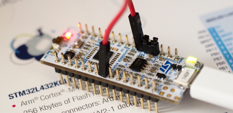
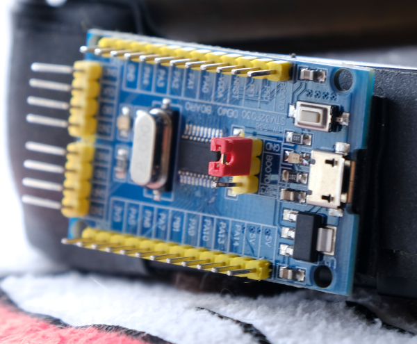
From the previous article, we have tried writing a program to study the elements of various files that we need, we found that there are quite a lot of details and steps. But it is an important basis for those who want to seriously and usefully study Cortex-M0 programming via STM32F030F4P6 (Figure 1), Cortex-M3 with STM32F103C (Figure 32) and Cortex-M4 with STM32F401CCU6 (Figure 27) to study of programming structure with programming tool STM32CubeIDE (Figure 2), which is the main tool used in this series of articles. This is because it combines ST’s complete development kit for ARM, including CubeMX for chip design, compiler toolkit, ST-Link program debugging tool and code editor in one tool, plus it supports both Windows, Linux and macOS operating systems.
This article is a series of programming articles focused on the Cortex-M0 via the STM32F030F4P6 or any other STM32 microcontroller based on CMSIS, an ARM firmware compiled from vivonomicon.com‘s series of Bare Metal: STM32 Programming articles without using the Arduino framework. In the article EP.1 is a matter of preparation. It consists of creating a link file to link different parts of the code together and the working part file. After that, the result file is uploaded into the microcontroller to complete the program development process.