บทความนี้เป็นการใช้งานบอร์ดไมโครคอนโทรลเลอร์ 32 บิตภายใต้สถาปัตยกรรม RISC แบบ Cortex-M0 ที่มีราคาประหยัดแต่การทำงานนับว่าดีกว่าบอร์ดที่เป็นแบบ 8 บิตพอสมควร ประกอบกับมีวิธีการใช้งานให้ศึกษาอยู่บนอินเทอร์เน็ตมากมาย แต่อย่างไรก็ดีทางทีมพวกเราก็สร้างเป็นทางเลือกหนึ่งสำหรับผู้ที่สนใจได้อ่านกัน โดยบทความเริ่มจากเนื้อหาเกี่ยวกับคุณสมบัติของไมโครคอนโทรลเลอร์ การติดตั้งบอร์ดให้ Arduino IDE รู้จัก และตัวอย่างโปรแกรมการสั่งท็อกเกิ้ลหลอดแอลอีดี การรับส่งข้อมูลผ่านพอร์ตสื่อสาร USART และการทดสอบการหา Prime number เพื่อดูความเร็วในการประมวลผลในแบบการวนรอบซ้ำ ๆ กัน

STM32F030F4P6
ไมโครคอนโทรลเลอร์ STM32F030F4P6 มีคุณสมบัติดังนี้
- ใช้แกน (Core) แบบ 32 บิต รองรับความถี่สัญญาณนาฬิกาสูงสุด 48MHz (8MHz x 6)
- หน่วยความจำ Flash ROM 16KB
- หน่วยความจำ SRAM 4KB
- GPIO จำนวน 15 ขา
- ADC ความละเอียด 12 บิต
- ทำงานที่แรงดัน 2.4-3.6 VDC
- รองรับการสื่อสาร USART, I2C และ SPI
- มี WDT
- บนบอร์ดมี External XTAL ความถี่ 8MHz
- บอร์ดมีตัวแปลงแรงดัน 5VDC ให้เป็น 3V3
- บอร์ดมีการแยกขาสำหรับ RS232 (ทำ ISP) และ SWD (สำหรับ ST-Link)
- บอร์ดมีสวิตช์ NRST สำหรับรีเซ็ตการทำงาน
- บอร์ดมี Jumper สำหรับเลือกแรงดันของขา Boot0 ให้เป็น 3V3 หรือ GND สำหรับโหลดอัพโหลดกับรันโปรแกรม
การติดตั้ง
การติดตั้งบอร์ดให้ Arduino IDE รู้จักต้องใช้ JSON ของ Arduino Core STM32 ดังนี้ใน Preferences ของ Arduino IDE
https://github.com/stm32duino/BoardManagerFiles/raw/master/package_stmicroelectronics_index.json
หลังจากนั้นเข้า Board Manager เพื่อติดตั้ง STM32 MCU based boards จะได้รายการดังภาพที่ 2 ให้เลือกบอร์ดเป็น STM32 boards groups (board to be selected from Tools submenu “Board part number”) / Generic STM32F0 series ดังภาพที่ 2 และตั้งค่าต่าง ๆ ดังภาพที่ 3


อุปกรณ์ที่ต้องใช้
การอัพโหลดโปรแกรมเข้าบอร์ดต้องใช้โปรแกรม STM32CubeProgrammer ที่ต้องติดตั้งเอาไว้ก่อนเพื่อสั่งงานอุปกรณ์ ST-Link สำหรับเชื่อมผ่านพอร์ต SWD ดังภาพที่ 4 และ 5


ที่บอร์ดของ STM32F030F4P6 มีขั้ว ISP และ SWD ดังภาพที่ 6 เพื่อใช้ต่อกับ USB-Serial และ ST-Link/V2 ดังภาพที่ 7 และ 8


โหมดอัพโหลด
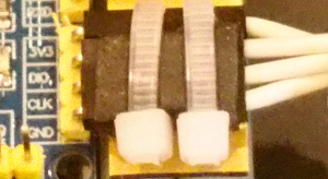
การอัพโหลดต้องเปลี่ยนโหมดด้วยการย้าย jumper ขั้ว BOOT0 มาไว้ ณ ตำแหน่ง 3V3 แล้วกดปุ่ม NRST ดังภาพที่ 9 และ 10


กรณีที่อัพโหลดไม่สำเร็จเนื่องจากไม่พบ STM32CubeProgrammer จะรายงานดังภาพที่ 11

ในบางกรณีที่ตั้งค่าทุกอย่างถูกต้องแต่ลืมเปลี่ยนโหมดการทำงานของ boot mode เป็นการอัพโหลดโปรแกรมจะรายงานดังภาพที่ 12

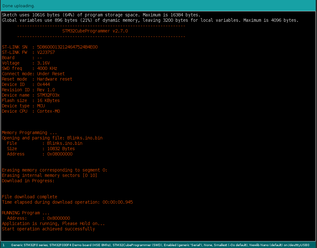
เมื่ออัพโหลดสำเร็จด้วยวิธีการอัพโหลดผ่าน RS232 จะรายงานผลดังภาพที่ 13 และกรณีที่ใช้ st-link จะรายงานดังภาพที่ 14

โหมดรันโปรแกรม
การรันทำโดยการย้ายตำแหน่งของ Jumper ขา Boot0 ไปไว้ที่ GND แล้วกดปุ่ม NRST ดังภาพที่ 15 และ 16


ตัวอย่างโปรแกรม
การ Blink
ตัวอย่างการสลับการส่งค่าของขา PA0, PA1, PA2, PA3 และ PA4 ระหว่าง 0 กับ 1 ทุก 500 มิลลิวินาทีที่ต่อเชื่อมกับภาค LED ของบอร์ดทดลอง ET-TEST I/O (ใช้มานานมาก) หรือ ET-TEST 10P/OUT เป็นดังนี้ และได้ผลลัพธ์ดังภาพที่ 17 และ 18
// Blink-4pins
uint8_t pins[] = {PA0, PA1, PA2, PA3, PA4};

void setup() {
  for (int idx = 0; idx < 5; idx++) {
    pinMode( pins[idx], OUTPUT );
  }

}

void loop() {
  for (int idx = 0; idx < 5; idx++) {
    digitalWrite( pins[idx], !digitalRead( pins[idx] ));
  }
  delay(500);
}

การใช้งาน RS232
จากโค้ดของ Brian Lavery ที่เขียนเกี่ยวกับการใช้งานบอร์ด STM32F030F4P6 กับ Arduino ทำให้สามารถใช้งานคลาส Serial ได้ง่ายโดยไม่ต้องเขียนโค้ดแก้ไขการทำงานของไลบรารี ซึ่ง Brain Lavery ได้เพิ่มโค้ดโปรแกรม 3 ไฟล์เข้ามาเพื่อควบคุมการทำงานของการสื่อสารอนุกรมของบอร์ดดังนี้
- โค้ดของไฟล์ charQueue.h เป็นดังนี้
// Very basic class (char) array-as-queue    BL Nov 2018
#define BUF_SIZE 40
class Queue
{
  private:
    bool _isFull() {
      return (_size == BUF_SIZE);
    };
    bool _isEmpty() {
      return (_size == 0);
    };
    char _buffer[BUF_SIZE];
    int _head;
    int _tail;
    int _size;

  public:
    Queue(void) {
      _head = 0;
      _tail = BUF_SIZE - 1;
      _size = 0;
    };
    bool enqueue(char ch) {
      if (_isFull())
        return false;
      _tail = (_tail + 1) % BUF_SIZE;
      _buffer[_tail] = ch;
      _size ++;
      return true;
    };
    int dequeue() {
      if (_isEmpty())
        return -1;
      char ch = _buffer[_head];
      _head = (_head + 1) % BUF_SIZE;
      _size --;
      return int(ch);
    };
};
ไฟล์ของ miniSerial.h เป็นดังนี้
// Serial BitBash for STM32F030F4P6

#pragma once

#include <Arduino.h>

#define BITDELAY  52
//  104 9600  baud  52 19200
//  not good above 19200

#define HEX 16
#define BIN 2
#define OCT 8

class MiniSerial
{
  public:
    MiniSerial(void);
    void begin(int baudrate = 19200, int txpin = PA9, int rxpin = PA10);
    int  read(void);
    void run(void);
    void write(unsigned char data);
    void print(double float_num, int prec = 2);	// uses lots of flash space! Avoid?
    void print(char* str);
    void print(int, int = DEC);
    void print(long, int = DEC);
    void println(double float_num, int prec = 2);
    void println(char* str = "");  // handles println() also
    void println(int, int = DEC);
    void println(long, int = DEC);

  private:
    int  _getChar(void);
    char _rx; // buffered chr
    char _rx1 = 0;
    int pinTx = -1; // -1 = not begin'd
    int pinRx ;
    unsigned long bitDelay = 52;  // //  104 9600  baud  52 19200

    enum { RXIDLE, READING, COMPLETE } ;
    enum { RXBUSY = -4, ERRNOTBEGIN = -3, ERRFRAME = -2,  RXNONE = -1 };
    int rxState = RXIDLE;
    unsigned long rx_chr = 0;
    unsigned long rx_reftime = 0;
    int rx_k;

};

extern MiniSerial mSerial;
#define Serial mSerial
ไฟล์ของ miniSerial.cpp เป็นดังนี้
// A bit-banged low-footprint serial transmit/receive
// primarily for low-memory STM32F030F4P6    BL Nov 2018
// By default uses PA9 as TX    PA10 as RX   -- regular 4-pin RX/TX end connector.
// 8 bit no parity.  19200 seems ideal (default)
// tx will block during character transfer (abt 0.6 mSec each chr at 19200)
// Your loop() must have free-running Serial.run(). No delay()s. Serial reception will suffer otherwise
// reception is buffered
// Transmit is not buffered, but does NOT stop reception processing.
// Functions in this "Serial" are an approximation to regular Serial calls.
// V 0.5.0

#include <miniSerial.h>
#include <charQueue.h>

Queue rxBuf;
//Queue txBuf;  // Buffered tx not currently implemented

MiniSerial::MiniSerial(void)
{
}

void MiniSerial::begin(int baud, int tx, int rx)
{
  pinRx = rx;
  pinTx = tx;
  bitDelay = (unsigned long) (1000000 / baud);
  pinMode(pinTx, OUTPUT);
  digitalWrite(pinTx, HIGH);
  pinMode(pinRx, INPUT);
}

int MiniSerial::read(void) // -1 =nothing/empty
{
  // fetch from buffer
  return rxBuf.dequeue();
}

void MiniSerial::run(void)  // MUST be called VERY frequently from your loop()
{
  int ch = _getChar();
  if (ch >= 0)
    rxBuf.enqueue((char) ch);
}

void MiniSerial::print(char* str)
{
  for (int i = 0; i < strlen(str); i++)
    write(str[i]);
}

void MiniSerial::println(char* str)
{
  print(str);
  print("\n");
}

void MiniSerial::print(int j, int base)
{
  char buffer[30];
  itoa(j, buffer, base);
  print(buffer);
}

void MiniSerial::print(long j, int base)  // but for stm32, both int and long are 32bit!
{
  print((int)j, base);
}

void MiniSerial::println(int j, int base)
{
  print(j, base);
  print("\n");
}

void MiniSerial::println(long j, int base)
{
  print((int)j, base); // long 32bit = int 32bit
  print("\n");
}

void MiniSerial::print(double float_num, int prec) {

  // precision - use 6 maximum
  int d = float_num; // get the integer part
  float f = float_num - d; // get the fractional part
  if (d == 0 && f < 0.0) {
    write('-');
    write('0');
    f *= -1;
  }
  else if (d < 0 && f < 0.0) {
    print(d);
    f *= -1;
  }
  else {
    print(d);
  }
  // only when fractional part > 0, we show decimal point
  if (f > 0.0) {
    write('.');
    int f_shift = 1;
    for (byte j = 0; j < prec; j++) {
      f_shift *= 10;
    }
    print((int)(f * f_shift));
  }
}

void MiniSerial::println(double float_num, int prec)
{
  print(float_num, prec);
  print("\n");
}


/////////////////////////         HARDWARE IO:

int MiniSerial::_getChar(void) // bit-bang rx
// >=0 good rx char
{
  if (pinTx < 0) return ERRNOTBEGIN;

  switch (rxState) {
    case RXIDLE :
      if (digitalRead(pinRx))  // still idle
        return RXNONE;
      // ok, we start rx:
      rx_reftime = micros() - bitDelay / 2;
      rx_chr = 0;
      rxState = READING;
      rx_k = 0;
      return RXBUSY;

    case  READING :  // 10 bit-length passes
      if (micros() - rx_reftime < bitDelay)
        return RXBUSY;
      rx_chr |= (digitalRead(pinRx) << rx_k++);
      rx_reftime += bitDelay;
      if (rx_k > 9)
        rxState = COMPLETE;
      return RXBUSY;

    case COMPLETE :
      rxState = RXIDLE;
      if ((rx_chr & 0b01000000001) != 0b01000000000)  // start & stop bits correct?
        return ERRFRAME;
      return (int) (rx_chr & 0x1FE) >> 1;  // a good chr received

    default:
      break;
  }
}


void MiniSerial::write(unsigned char data)    // TX one byte
{
  if (pinTx < 0) return;

  int chr = (data << 1) | 0b011000000000 ;
  unsigned long starttime = micros();

  for (int i = 11; i > 0; i--)      // 1 start (0), 8 data bits, 2 stop (11)
  {
    digitalWrite(pinTx, chr & 1);
    chr = (chr >> 1);
    while (micros() - starttime < bitDelay) {
      run(); // keep processing incoming characters!!
    }
    starttime += bitDelay;
  }
}


MiniSerial mSerial;
ตัวอย่างการใช้งาน miniSerial พร้อมทั้งกะพริบหลอด LED ที่เชื่อมต่อกับ PA3
#include <miniSerial.h>
unsigned long t0;

void setup(void)
{
  Serial.begin(9600);
  // Serial.begin(19200, PA2, PA3);
  pinMode(LED_BUILTIN, OUTPUT);

  delay(500);  // IDE's serial terminal may take a bit of wakeup time. Don't lose first chrs.
  t0 = millis();   // used by loop()
  Serial.print("\nminiSerial RX/TX demo - software based, non native Serial port.\n");
  Serial.print("Transmit is unbuffered, Receive is buffered.\n");
  Serial.print("Type some input. Demo: Buffer is read each second.\n");

}

void loop()
{
  Serial.run();    // ESSENTIAL FOR RX BUFFERING SYSTEM. and no delay() allowed below.

  // can't use delay() so delay by a non-blocking method !!!
  unsigned long t1 = millis();
  if (t1 - t0 < 1000) // 1 sec
    return;
  t0 = t1;

  // here only every 1 sec:
  digitalWrite(LED_BUILTIN, 1 - digitalRead(LED_BUILTIN));
  int ch;
  while ((ch = Serial.read()) >= 0) // read any/all chrs from buffer
  {
    Serial.print("From buffer: ");
    Serial.println(ch);   // send it back out
  }
}
การหา Prime Number
จากตัวอย่างการใช้ RS232 เมื่อรวมกับการหา Prime Number จากบทความ LGT8F328P และ ET-BASE AVR EASY4809 เมื่อนำมาใช้กับ STM32F030F4P6 จะเป็นดังนี้ และผลของการทำงานเป็นดังภาพที่ 19
#include <miniSerial.h>
#include <math.h>

bool isPrimeNumber(uint16_t x) {
  uint16_t i;
  for (i = 2; i < x; i++) {
    if (x % i == 0) {
      return false;
    }
  }
  if (i == x)
    return true;
  return false;
}

int counter = 0;
uint32_t t0, t1;
void testPrimeNumber(uint16_t maxN) {
  t0 = millis();
  for (uint16_t n = 2; n < maxN; n++) {
    if (isPrimeNumber(n)) {
      counter++;
    }
  }
  t1 = millis();
}

void setup(void)
{
  Serial.begin(9600);
  testPrimeNumber(2000);
  Serial.print("Found ");
  Serial.print(counter, DEC);
  Serial.print(" in ");
  Serial.print(int(fabs(t1 - t0)), DEC);
  Serial.println(" milliseconds.");
}
void loop(void)
{
}
I2C Client
จากบทความการสั่งงาน esp8266/esp32 ที่ใช้ MicroPython แล้วสั่งงานควบคุม Arduino Uno ผ่านทางบัส I2C นั้น เมื่อทางทีมเราได้ทดลองกับ stm32f030f4p6 โดยโค้ดของ Micropython เป็นดังนี้
#code-02 โค้ดของ ESP8266
from machine import Pin, I2C
import time

sclPin = Pin(5)
sdaPin = Pin(4)
devAddr = const(0x17)
devLedAddr = const(0x00)
devSpkAddr = const(0x01)
devBuffer = bytearray(2)

i2c = I2C(sda = sdaPin, scl = sclPin )
time.sleep_ms(250)
print("Begin of Program")
print(i2c.scan())
for i in range(10): # blink
    devBuffer[0] = devLedAddr
    devBuffer[1] = 0
    i2c.writeto(devAddr, devBuffer)
    time.sleep_ms(100)
    devBuffer[1] = 1
    i2c.writeto(devAddr, devBuffer)
    time.sleep_ms(100)
print("End of Program")
และโค้ดการทำงานฝั่ง stm32 เพื่อรับคำสั่งจาก I2C สำหรับเปิดและปิด LED ที่ต่ออยู่กับขา PA4 และการเชื่อมต่อกับบัส I2C กระทำโดยใช้ขา PA10 กับขา PA9
////////////////////////////////////////////////////////////////////////
// i2c client
// STM32F030F4P6
// Address 0x17
// Input
//     Byte 1
//        0 Blink LED : PA4
// (C) 2021, JarutEx
////////////////////////////////////////////////////////////////////////
#include <Wire.h>
int unoAddr = 0x17;
#define ledPin PA4

void i2cReceive( int bytes ) {
  uint8_t dInput = Wire.read(); // command
  uint8_t dValue = Wire.read(); // argument
  if (dInput == 0) { // Flash
    if (dValue == 0) {
      digitalWrite(ledPin, HIGH);
    } else if (dValue == 1) {
      digitalWrite(ledPin, LOW);
    }
  }
}
void i2cRequest() {
  Wire.write(0x00);
}
void setup() {
  pinMode( ledPin, OUTPUT );
  digitalWrite( ledPin, HIGH); // off LED
   Wire.begin(unoAddr);
  Wire.onReceive(i2cReceive);
  Wire.onRequest(i2cRequest);
}
void loop() {
}
สรุป
จากบทความนี้จะพบว่าการใช้งาน STM32F030F4P6 นั้นมีขั้นตอนที่ต้องกระทำอย่างเป็นนิจคือ เลือกโหมดว่ากำลังจะอัพโหลดโปรแกรมหรือรันโปรแกรม ต้องเตรียมสาย Serial เพื่อทำ ISP หรือใช้ ST-Link ผ่าน SWD ต้องเลือกโหมดทำงานของ STM32CubeProgrammer ว่าเป็น Serial หรือ SWD ให้ตรงกัน ที่สำคัญต้องเพิ่มโค้ดของ Brain Lavery เพื่อสื่อสาร RS232 ได้ถูกต้อง จะเห็นว่ามีขั้นตอนที่ละเอียดกว่าบอร์ด Arduino รุ่นอื่น ๆ และเมื่อเทียบกับบอร์ด STM32 ที่ทาง ETT ออกแบบให้สามารถเลือกโหมดด้วยการกดสวิตช์และใช้สาย Serial แบบ RS232 ในการอัพโหลดนับว่าสะดวกกว่า แต่อย่างไรก็ดี ด้วยราคาและประสิทธิภาพที่นับว่าดีกว่า Arduino แบบ 8 บิต จึงนับได้ว่าเป็นทางเลือกที่ดีทางหนึ่งสำหรับการเลือกเส้นทางการพัฒนางานสมองกลฝังตัวด้วย Cortex-M0 สุดท้ายนี้ขอให้สนุกกับการเขียนโปรแกรมครับ
หากท่านอยากพูดคุยหรือแลกเปลี่ยนกันสามารถคอมเมนท์ไว้ได้เลยครับ
แหล่งอ้างอิง
(C) 2020-2021, โดย อ.ดนัย เจษฎาฐิติกุล/อ.จารุต บุศราทิจ
ปรับปรุงเมื่อ 2021-06-29, 2021-07-03, 2021-10-06