This article is about using a 32-bit microcontroller board under the Cortex-M0 architecture RISC that is economical but the performance is considerably better than the 8-bit board. However, our team has created an alternative for those who are interested in reading. The article starts with the content about the features of microcontrollers, board installation for Arduino IDE to know and example code to toggle LED, traffic through the USART communication port and Prime numbering test to see the processing speed in an iterative loop.

STM32F030F4P6
STM32F030F4P6 has the following features
- Uses a 32-bit core, supports a maximum clock frequency of 48MHz (8MHz x 6).
- 16KB Flash ROM
- 4KB SRAM
- 15 pins of GPIO
- 12-bits ADC
- operates at 2.4-3.6 VDC
- Supports USART, I2C and SPI
- has a WDT
- 8MHZ external XTAL
- The board has a voltage converter 5VDC to 3V3.
- The board has separate pins for RS232 (for ISP) and SWD (for ST-Link).
- The board has a NRST switch for resetting the operation.
- The board has a Jumper for selecting the voltage of Pin Boot0 to be 3V3 or GND for uploading and running the program.
Installation
Installing the board to be recognized by the Arduino IDE requires JSON of the Arduino Core STM32 as follows in the Preferences of the Arduino IDE.
https://github.com/stm32duino/BoardManagerFiles/raw/master/package_stmicroelectronics_index.json
After that, go to Board Manager to install STM32 MCU based boards, you will get a list as shown in Figure 2, select the board as STM32 boards groups (board to be selected from Tools submenu “Board part number”) / Generic STM32F0 series as shown in Figure 2 and set the values as shown in Figure 3.


Equipment
Uploading a program to the board requires a program STM32CubeProgrammer that must be installed before for operate ST-Link devices for connecting via SWD port as shown in Figures 4 and 5.


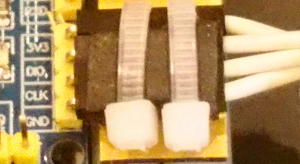
On the board of STM32F030F4P6, there are connectors ISP and SWD as shown in Figure 6 to connect with USB-Serial and ST-Link/V2 as shown in Figures 7 and 8.


Upload mode
Uploading must change the mode by moving the jumper BOOT0 connector to position 3V3 and press the NRST button as shown in Figures 9 and 10.


If the upload failed because it did not found STM32CubeProgrammer, it will report as shown in Figure 11.

In some cases, when everything is set correctly, but forget to change the boot mode to upload, the program will report as shown in Figure 12.

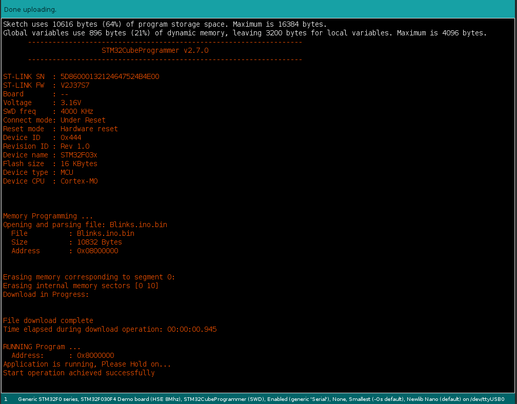
When uploading successfully by uploading via RS232, the result will be reported as shown in Figure 13, and in the case of using st-link, it will be reported as shown in Figure 14.

Program running mode
Program running is done by moving the Jumper Pin Boot0 to GND and pressing the NRST button as shown in Figures 15 and 16.


Example Code
Blink
An example of switching the value of pins PA0, PA1, PA2, PA3 and PA4 between 0 and 1 every 500 milliseconds while connected to the LED part of the test board ET-TEST I/O (long time use) or ET-TEST. 10P/OUT is as follows, and the result is as shown in Figures 17 and 18.
// Blink-4pins
uint8_t pins[] = {PA0, PA1, PA2, PA3, PA4};

void setup() {
  for (int idx = 0; idx < 5; idx++) {
    pinMode( pins[idx], OUTPUT );
  }

}

void loop() {
  for (int idx = 0; idx < 5; idx++) {
    digitalWrite( pins[idx], !digitalRead( pins[idx] ));
  }
  delay(500);
}

Using RS232
Brian Lavery‘s code on STM32F030F4P6 usage with Arduino makes it easy to use Serial classes without having to edit the library code. Brain Lavery has added 3 program code files to control the serial communication of the board as follows.
// Very basic class (char) array-as-queue    BL Nov 2018
#define BUF_SIZE 40
class Queue
{
  private:
    bool _isFull() {
      return (_size == BUF_SIZE);
    };
    bool _isEmpty() {
      return (_size == 0);
    };
    char _buffer[BUF_SIZE];
    int _head;
    int _tail;
    int _size;

  public:
    Queue(void) {
      _head = 0;
      _tail = BUF_SIZE - 1;
      _size = 0;
    };
    bool enqueue(char ch) {
      if (_isFull())
        return false;
      _tail = (_tail + 1) % BUF_SIZE;
      _buffer[_tail] = ch;
      _size ++;
      return true;
    };
    int dequeue() {
      if (_isEmpty())
        return -1;
      char ch = _buffer[_head];
      _head = (_head + 1) % BUF_SIZE;
      _size --;
      return int(ch);
    };
};
// Serial BitBash for STM32F030F4P6

#pragma once

#include <Arduino.h>

#define BITDELAY  52
//  104 9600  baud  52 19200
//  not good above 19200

#define HEX 16
#define BIN 2
#define OCT 8

class MiniSerial
{
  public:
    MiniSerial(void);
    void begin(int baudrate = 19200, int txpin = PA9, int rxpin = PA10);
    int  read(void);
    void run(void);
    void write(unsigned char data);
    void print(double float_num, int prec = 2);	// uses lots of flash space! Avoid?
    void print(char* str);
    void print(int, int = DEC);
    void print(long, int = DEC);
    void println(double float_num, int prec = 2);
    void println(char* str = "");  // handles println() also
    void println(int, int = DEC);
    void println(long, int = DEC);

  private:
    int  _getChar(void);
    char _rx; // buffered chr
    char _rx1 = 0;
    int pinTx = -1; // -1 = not begin'd
    int pinRx ;
    unsigned long bitDelay = 52;  // //  104 9600  baud  52 19200

    enum { RXIDLE, READING, COMPLETE } ;
    enum { RXBUSY = -4, ERRNOTBEGIN = -3, ERRFRAME = -2,  RXNONE = -1 };
    int rxState = RXIDLE;
    unsigned long rx_chr = 0;
    unsigned long rx_reftime = 0;
    int rx_k;

};

extern MiniSerial mSerial;
#define Serial mSerial
// A bit-banged low-footprint serial transmit/receive
// primarily for low-memory STM32F030F4P6    BL Nov 2018
// By default uses PA9 as TX    PA10 as RX   -- regular 4-pin RX/TX end connector.
// 8 bit no parity.  19200 seems ideal (default)
// tx will block during character transfer (abt 0.6 mSec each chr at 19200)
// Your loop() must have free-running Serial.run(). No delay()s. Serial reception will suffer otherwise
// reception is buffered
// Transmit is not buffered, but does NOT stop reception processing.
// Functions in this "Serial" are an approximation to regular Serial calls.
// V 0.5.0

#include <miniSerial.h>
#include <charQueue.h>

Queue rxBuf;
//Queue txBuf;  // Buffered tx not currently implemented

MiniSerial::MiniSerial(void)
{
}

void MiniSerial::begin(int baud, int tx, int rx)
{
  pinRx = rx;
  pinTx = tx;
  bitDelay = (unsigned long) (1000000 / baud);
  pinMode(pinTx, OUTPUT);
  digitalWrite(pinTx, HIGH);
  pinMode(pinRx, INPUT);
}

int MiniSerial::read(void) // -1 =nothing/empty
{
  // fetch from buffer
  return rxBuf.dequeue();
}

void MiniSerial::run(void)  // MUST be called VERY frequently from your loop()
{
  int ch = _getChar();
  if (ch >= 0)
    rxBuf.enqueue((char) ch);
}

void MiniSerial::print(char* str)
{
  for (int i = 0; i < strlen(str); i++)
    write(str[i]);
}

void MiniSerial::println(char* str)
{
  print(str);
  print("\n");
}

void MiniSerial::print(int j, int base)
{
  char buffer[30];
  itoa(j, buffer, base);
  print(buffer);
}

void MiniSerial::print(long j, int base)  // but for stm32, both int and long are 32bit!
{
  print((int)j, base);
}

void MiniSerial::println(int j, int base)
{
  print(j, base);
  print("\n");
}

void MiniSerial::println(long j, int base)
{
  print((int)j, base); // long 32bit = int 32bit
  print("\n");
}

void MiniSerial::print(double float_num, int prec) {

  // precision - use 6 maximum
  int d = float_num; // get the integer part
  float f = float_num - d; // get the fractional part
  if (d == 0 && f < 0.0) {
    write('-');
    write('0');
    f *= -1;
  }
  else if (d < 0 && f < 0.0) {
    print(d);
    f *= -1;
  }
  else {
    print(d);
  }
  // only when fractional part > 0, we show decimal point
  if (f > 0.0) {
    write('.');
    int f_shift = 1;
    for (byte j = 0; j < prec; j++) {
      f_shift *= 10;
    }
    print((int)(f * f_shift));
  }
}

void MiniSerial::println(double float_num, int prec)
{
  print(float_num, prec);
  print("\n");
}


/////////////////////////         HARDWARE IO:

int MiniSerial::_getChar(void) // bit-bang rx
// >=0 good rx char
{
  if (pinTx < 0) return ERRNOTBEGIN;

  switch (rxState) {
    case RXIDLE :
      if (digitalRead(pinRx))  // still idle
        return RXNONE;
      // ok, we start rx:
      rx_reftime = micros() - bitDelay / 2;
      rx_chr = 0;
      rxState = READING;
      rx_k = 0;
      return RXBUSY;

    case  READING :  // 10 bit-length passes
      if (micros() - rx_reftime < bitDelay)
        return RXBUSY;
      rx_chr |= (digitalRead(pinRx) << rx_k++);
      rx_reftime += bitDelay;
      if (rx_k > 9)
        rxState = COMPLETE;
      return RXBUSY;

    case COMPLETE :
      rxState = RXIDLE;
      if ((rx_chr & 0b01000000001) != 0b01000000000)  // start & stop bits correct?
        return ERRFRAME;
      return (int) (rx_chr & 0x1FE) >> 1;  // a good chr received

    default:
      break;
  }
}


void MiniSerial::write(unsigned char data)    // TX one byte
{
  if (pinTx < 0) return;

  int chr = (data << 1) | 0b011000000000 ;
  unsigned long starttime = micros();

  for (int i = 11; i > 0; i--)      // 1 start (0), 8 data bits, 2 stop (11)
  {
    digitalWrite(pinTx, chr & 1);
    chr = (chr >> 1);
    while (micros() - starttime < bitDelay) {
      run(); // keep processing incoming characters!!
    }
    starttime += bitDelay;
  }
}


MiniSerial mSerial;
Example of using miniSerial with blinking LED connected to PA3.
#include <miniSerial.h>
unsigned long t0;

void setup(void)
{
  Serial.begin(9600);
  // Serial.begin(19200, PA2, PA3);
  pinMode(LED_BUILTIN, OUTPUT);

  delay(500);  // IDE's serial terminal may take a bit of wakeup time. Don't lose first chrs.
  t0 = millis();   // used by loop()
  Serial.print("\nminiSerial RX/TX demo - software based, non native Serial port.\n");
  Serial.print("Transmit is unbuffered, Receive is buffered.\n");
  Serial.print("Type some input. Demo: Buffer is read each second.\n");

}

void loop()
{
  Serial.run();    // ESSENTIAL FOR RX BUFFERING SYSTEM. and no delay() allowed below.

  // can't use delay() so delay by a non-blocking method !!!
  unsigned long t1 = millis();
  if (t1 - t0 < 1000) // 1 sec
    return;
  t0 = t1;

  // here only every 1 sec:
  digitalWrite(LED_BUILTIN, 1 - digitalRead(LED_BUILTIN));
  int ch;
  while ((ch = Serial.read()) >= 0) // read any/all chrs from buffer
  {
    Serial.print("From buffer: ");
    Serial.println(ch);   // send it back out
  }
}
Finding Prime Number
The example of using RS232 when combined with finding Prime Number from article LGT8F328P and ET-BASE AVR EASY4809 when used with STM32F030F4P6 is as follows, and the result of the code is as shown in Figure 19.
#include <miniSerial.h>
#include <math.h>

bool isPrimeNumber(uint16_t x) {
  uint16_t i;
  for (i = 2; i < x; i++) {
    if (x % i == 0) {
      return false;
    }
  }
  if (i == x)
    return true;
  return false;
}

int counter = 0;
uint32_t t0, t1;
void testPrimeNumber(uint16_t maxN) {
  t0 = millis();
  for (uint16_t n = 2; n < maxN; n++) {
    if (isPrimeNumber(n)) {
      counter++;
    }
  }
  t1 = millis();
}

void setup(void)
{
  Serial.begin(9600);
  testPrimeNumber(2000);
  Serial.print("Found ");
  Serial.print(counter, DEC);
  Serial.print(" in ");
  Serial.print(int(fabs(t1 - t0)), DEC);
  Serial.println(" milliseconds.");
}
void loop(void)
{
}
I2C Client
From the esp8266/esp32 controlling article with MicroPython and controls Arduino Uno via the I2C bus, we test with stm32f030f4p6 with Micropython code as follows.
#code-02 โค้ดของ ESP8266
from machine import Pin, I2C
import time

sclPin = Pin(5)
sdaPin = Pin(4)
devAddr = const(0x17)
devLedAddr = const(0x00)
devSpkAddr = const(0x01)
devBuffer = bytearray(2)

i2c = I2C(sda = sdaPin, scl = sclPin )
time.sleep_ms(250)
print("Begin of Program")
print(i2c.scan())
for i in range(10): # blink
    devBuffer[0] = devLedAddr
    devBuffer[1] = 0
    i2c.writeto(devAddr, devBuffer)
    time.sleep_ms(100)
    devBuffer[1] = 1
    i2c.writeto(devAddr, devBuffer)
    time.sleep_ms(100)
print("End of Program")
And stm32 code to receive commands from I2C for turning on and off LEDs connected to pin PA4 and connecting to the I2C bus by using pin PA10 and pin PA9.
////////////////////////////////////////////////////////////////////////
// i2c client
// STM32F030F4P6
// Address 0x17
// Input
//     Byte 1
//        0 Blink LED : PA4
// (C) 2021, JarutEx
////////////////////////////////////////////////////////////////////////
#include <Wire.h>
int unoAddr = 0x17;
#define ledPin PA4

void i2cReceive( int bytes ) {
  uint8_t dInput = Wire.read(); // command
  uint8_t dValue = Wire.read(); // argument
  if (dInput == 0) { // Flash
    if (dValue == 0) {
      digitalWrite(ledPin, HIGH);
    } else if (dValue == 1) {
      digitalWrite(ledPin, LOW);
    }
  }
}
void i2cRequest() {
  Wire.write(0x00);
}
void setup() {
  pinMode( ledPin, OUTPUT );
  digitalWrite( ledPin, HIGH); // off LED
   Wire.begin(unoAddr);
  Wire.onReceive(i2cReceive);
  Wire.onRequest(i2cRequest);
}
void loop() {
}
Conclusion
From this article, you will find that the use of STM32F030F4P6 needs steps that must be done regularly. Choose a mode of whether to upload the program or run the program. A serial cable must be prepared for ISP or ST-Link via SWD, STM32CubeProgrammer mode must be matched whether it’s Serial or SWD. It is important to add Brain Lavery code to communicate RS232 correctly. You can see that there is a more detailed process than other Arduino boards and compared to the STM32 board that ETT designed to be able to choose the mode by pressing the switch and using the RS232 serial cable to upload, it’s more convenient. However, With the price and performance that is better than 8-bit Arduino, it can be considered as a good choice for choosing the path of development of embedded work with Cortex-M0. Finally, have fun with programming.
If you want to discuss or talk with us, feel free to comments below!
แหล่งอ้างอิง
(C) 2020-2021, By Jarut Busarathid and Dania Jedsadathitikul
Updated 2021-10-12