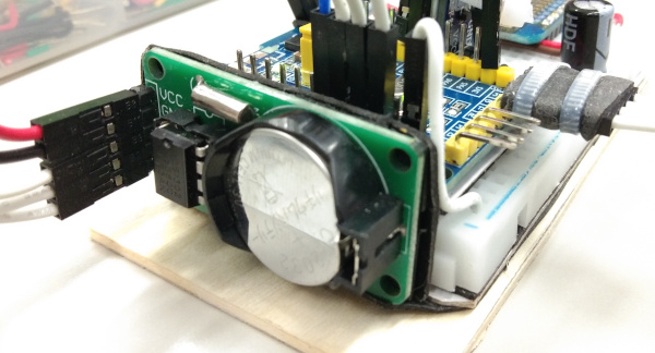
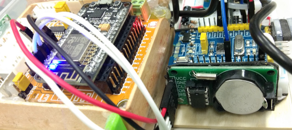
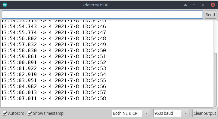
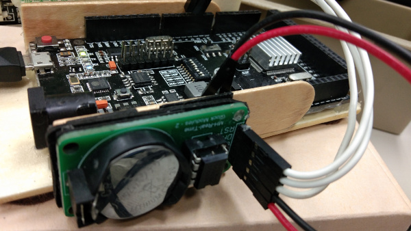
From the article programming Python on Micropython to use RTC number DS1302, this time, we change the programming language to C++ for Arduino by using STM32F030F4P6 Cortex-M0, esp8266 and Arduino Mega as a worker instead of ESP32 as shown in Figures 1, 2 and 6 by show the report on the RS232 port to display the date and time as shown in Figure 4.
Code
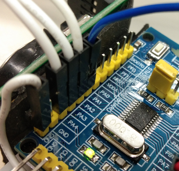
Program code for reading and writing date/time with IC ds1302’s RTC is as follows. It is connected to the microcontroller via pins PA2, PA3 and PA4 to SCLK, IO and CE respectively as shown in Figure 3.
// ds1302
// (C) 2021, by JarutEx (https://ww.jarutex.com)
#include <miniSerial.h>

#define PIN_CE PA4
#define PIN_SCLK PA2
#define PIN_IO PA3
#define REG_SECOND  0x80
#define REG_MINUTE  0x82
#define REG_HOUR    0x84
#define REG_DAY     0x86
#define REG_MONTH   0x88
#define REG_WEEKDAY 0x8A
#define REG_YEAR    0x8C
#define REG_WP      0x8E
#define REG_CTRL    0x90
#define REG_RAM     0xC0
uint8_t rtc[] = {0, 0, 0, 0, 0, 0, 0}; // y/m/d/dw/h/mi/s

inline void disCe() {
  digitalWrite( PIN_CE, LOW );
}

inline void enaCe() {
  digitalWrite( PIN_CE, HIGH );
}

inline void pulse() {
  digitalWrite( PIN_SCLK, HIGH );
  digitalWrite( PIN_SCLK, LOW );
}

uint8_t dec2bcd(uint8_t n) {
  return ((int)(n / 10) * 16 + (n % 10));
}

uint8_t bcd2dec( uint8_t n ) {
  return ((int)(n / 16 * 10) + (n % 16));
}

void write( uint8_t data ) {
  uint8_t dataBit;
  pinMode( PIN_IO, OUTPUT );
  for (int i = 0; i < 8; i++) {
    dataBit = (data & 0x01);
    data >>= 1;
    digitalWrite( PIN_IO, dataBit );
    pulse();
  }
}

uint8_t read() {
  uint8_t byteData = 0x00;
  uint8_t bitData;
  pinMode( PIN_IO, INPUT );
  for (int i = 0; i < 8; i++) {
    bitData = digitalRead( PIN_IO ) & 0x01;
    bitData <<= i;
    byteData |= bitData;
    pulse();
  }
  return byteData;
}

void set(uint8_t reg, uint8_t value) {
  enaCe();
  write(reg);
  write(value);
  disCe();
}

uint8_t get(uint8_t reg) {
  uint8_t value = 0;
  enaCe();
  write(reg + 1);
  value = read();
  disCe();
  return value;
}

void now() {
  rtc[0] = bcd2dec( get(REG_YEAR) );
  rtc[1] = bcd2dec( get(REG_MONTH) );
  rtc[2] = bcd2dec( get(REG_DAY) );
  rtc[3] = bcd2dec( get(REG_WEEKDAY) );
  rtc[4] = bcd2dec( get(REG_HOUR) );
  rtc[5] = bcd2dec( get(REG_MINUTE) );
  rtc[6] = bcd2dec( get(REG_SECOND) );
}

void adjust(uint8_t day, uint8_t month, uint16_t year,
            uint8_t dow, uint8_t hour, uint8_t minute, uint8_t second) {
  // convert
  year -= 2000;
  year &= 0xff;
  year = dec2bcd((uint8_t)year);
  month = dec2bcd(month);
  day = dec2bcd(day);
  dow = dec2bcd(dow);
  minute = dec2bcd(minute);
  hour = hour & 0x1F;
  hour = dec2bcd(hour);
  second = dec2bcd(second);
  // adjust
  set(REG_YEAR, year);
  set(REG_MONTH, month);
  set(REG_DAY, day);
  set(REG_WEEKDAY, dow);
  set(REG_HOUR, hour);
  set(REG_MINUTE, minute);
  set(REG_SECOND, second);
}

void show() {
  Serial.print( rtc[3] );
  Serial.print(" ");
  Serial.print( rtc[0]+2000 );
  Serial.print("-");
  Serial.print( rtc[1] );
  Serial.print("-");
  Serial.print( rtc[2] );
  Serial.print(" ");
  Serial.print( rtc[4] );
  Serial.print(":");
  Serial.print( rtc[5] );
  Serial.print(":");
  Serial.print( rtc[6] );
  Serial.println("");
}

void setup(void)
{
  Serial.begin(9600);
  // Serial.begin(19200, PA2, PA3);
  // Setting
  pinMode( PIN_IO, OUTPUT );
  pinMode( PIN_SCLK, OUTPUT );
  pinMode( PIN_CE, OUTPUT );
  disCe();
  digitalWrite( PIN_SCLK, LOW );

  adjust( 8, 7, 2021, 4, 13, 53, 0);
}

void loop()
{
  Serial.run();
  now();
  show();
  delay(1000);
}
The result is shown in figure 4.
Example code for esp8266
In the case of using esp8266, we choose pins D1, D2 and D4 or GPIO5, GPIO4 and GPIO2 to connect to pins SCLK, IO and CE to use DS1302. The code is as follows.
// ds1302/esp8266
// (C) 2021, by JarutEx (https://ww.jarutex.com)

#define PIN_CE 2 // D4
#define PIN_SCLK 5 // D1
#define PIN_IO 4 // D2

#define REG_SECOND  0x80
#define REG_MINUTE  0x82
#define REG_HOUR    0x84
#define REG_DAY     0x86
#define REG_MONTH   0x88
#define REG_WEEKDAY 0x8A
#define REG_YEAR    0x8C
#define REG_WP      0x8E
#define REG_CTRL    0x90
#define REG_RAM     0xC0
uint8_t rtc[] = {0, 0, 0, 0, 0, 0, 0}; // y/m/d/dw/h/mi/s

inline void disCe() {
  digitalWrite( PIN_CE, LOW );
}

inline void enaCe() {
  digitalWrite( PIN_CE, HIGH );
}

inline void pulse() {
  digitalWrite( PIN_SCLK, HIGH );
  digitalWrite( PIN_SCLK, LOW );
}

uint8_t dec2bcd(uint8_t n) {
  return ((int)(n / 10) * 16 + (n % 10));
}

uint8_t bcd2dec( uint8_t n ) {
  return ((int)(n / 16 * 10) + (n % 16));
}

void write( uint8_t data ) {
  uint8_t dataBit;
  pinMode( PIN_IO, OUTPUT );
  for (int i = 0; i < 8; i++) {
    dataBit = (data & 0x01);
    data >>= 1;
    digitalWrite( PIN_IO, dataBit );
    pulse();
  }
}

uint8_t read() {
  uint8_t byteData = 0x00;
  uint8_t bitData;
  pinMode( PIN_IO, INPUT );
  for (int i = 0; i < 8; i++) {
    bitData = digitalRead( PIN_IO ) & 0x01;
    bitData <<= i;
    byteData |= bitData;
    pulse();
  }
  return byteData;
}

void set(uint8_t reg, uint8_t value) {
  enaCe();
  write(reg);
  write(value);
  disCe();
}

uint8_t get(uint8_t reg) {
  uint8_t value = 0;
  enaCe();
  write(reg + 1);
  value = read();
  disCe();
  return value;
}

void now() {
  rtc[0] = bcd2dec( get(REG_YEAR) );
  rtc[1] = bcd2dec( get(REG_MONTH) );
  rtc[2] = bcd2dec( get(REG_DAY) );
  rtc[3] = bcd2dec( get(REG_WEEKDAY) );
  rtc[4] = bcd2dec( get(REG_HOUR) );
  rtc[5] = bcd2dec( get(REG_MINUTE) );
  rtc[6] = bcd2dec( get(REG_SECOND) );
}

void adjust(uint8_t day, uint8_t month, uint16_t year,
            uint8_t dow, uint8_t hour, uint8_t minute, uint8_t second) {
  // convert
  year -= 2000;
  year &= 0xff;
  year = dec2bcd((uint8_t)year);
  month = dec2bcd(month);
  day = dec2bcd(day);
  dow = dec2bcd(dow);
  minute = dec2bcd(minute);
  hour = hour & 0x1F;
  hour = dec2bcd(hour);
  second = dec2bcd(second);
  // adjust
  set(REG_YEAR, year);
  set(REG_MONTH, month);
  set(REG_DAY, day);
  set(REG_WEEKDAY, dow);
  set(REG_HOUR, hour);
  set(REG_MINUTE, minute);
  set(REG_SECOND, second);
}

void show() {
  Serial.print( rtc[3] );
  Serial.print(" ");
  Serial.print( rtc[0]+2000 );
  Serial.print("-");
  Serial.print( rtc[1] );
  Serial.print("-");
  Serial.print( rtc[2] );
  Serial.print(" ");
  Serial.print( rtc[4] );
  Serial.print(":");
  Serial.print( rtc[5] );
  Serial.print(":");
  Serial.print( rtc[6] );
  Serial.println("");
}

void setup(void)
{
  Serial.begin(9600);

  pinMode( PIN_IO, OUTPUT );
  pinMode( PIN_SCLK, OUTPUT );
  pinMode( PIN_CE, OUTPUT );
  disCe();
  digitalWrite( PIN_SCLK, LOW );

  adjust( 8, 7, 2021, 4, 13, 53, 0);
}

void loop()
{
  now();
  show();
  delay(1000);
}
The setting of Arduino IDE is as shown in the figure 5.
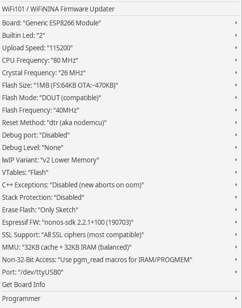
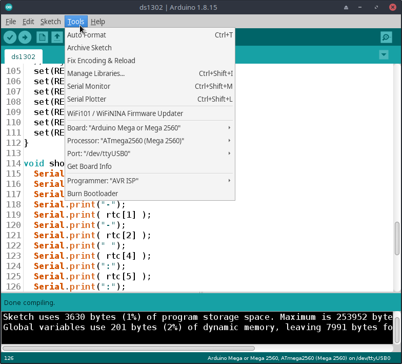
Example code for Arduino Mega
When trying to change the pin values for SCLK, IO and CE to D2, D3 and D4 of Arduino Mega as shown in figure 6 and configure as shown in figure 7, the program code is as follows.
// ds1302/Arduino Mega
// (C) 2021, by JarutEx (https://ww.jarutex.com)

#define PIN_CE 4
#define PIN_SCLK 2
#define PIN_IO 3

#define REG_SECOND  0x80
#define REG_MINUTE  0x82
#define REG_HOUR    0x84
#define REG_DAY     0x86
#define REG_MONTH   0x88
#define REG_WEEKDAY 0x8A
#define REG_YEAR    0x8C
#define REG_WP      0x8E
#define REG_CTRL    0x90
#define REG_RAM     0xC0
uint8_t rtc[] = {0, 0, 0, 0, 0, 0, 0}; // y/m/d/dw/h/mi/s

inline void disCe() {
  digitalWrite( PIN_CE, LOW );
}

inline void enaCe() {
  digitalWrite( PIN_CE, HIGH );
}

inline void pulse() {
  digitalWrite( PIN_SCLK, HIGH );
  digitalWrite( PIN_SCLK, LOW );
}

uint8_t dec2bcd(uint8_t n) {
  return ((int)(n / 10) * 16 + (n % 10));
}

uint8_t bcd2dec( uint8_t n ) {
  return ((int)(n / 16 * 10) + (n % 16));
}

void write( uint8_t data ) {
  uint8_t dataBit;
  pinMode( PIN_IO, OUTPUT );
  for (int i = 0; i < 8; i++) {
    dataBit = (data & 0x01);
    data >>= 1;
    digitalWrite( PIN_IO, dataBit );
    pulse();
  }
}

uint8_t read() {
  uint8_t byteData = 0x00;
  uint8_t bitData;
  pinMode( PIN_IO, INPUT );
  for (int i = 0; i < 8; i++) {
    bitData = digitalRead( PIN_IO ) & 0x01;
    bitData <<= i;
    byteData |= bitData;
    pulse();
  }
  return byteData;
}

void set(uint8_t reg, uint8_t value) {
  enaCe();
  write(reg);
  write(value);
  disCe();
}

uint8_t get(uint8_t reg) {
  uint8_t value = 0;
  enaCe();
  write(reg + 1);
  value = read();
  disCe();
  return value;
}

void now() {
  rtc[0] = bcd2dec( get(REG_YEAR) );
  rtc[1] = bcd2dec( get(REG_MONTH) );
  rtc[2] = bcd2dec( get(REG_DAY) );
  rtc[3] = bcd2dec( get(REG_WEEKDAY) );
  rtc[4] = bcd2dec( get(REG_HOUR) );
  rtc[5] = bcd2dec( get(REG_MINUTE) );
  rtc[6] = bcd2dec( get(REG_SECOND) );
}

void adjust(uint8_t day, uint8_t month, uint16_t year,
            uint8_t dow, uint8_t hour, uint8_t minute, uint8_t second) {
  // convert
  year -= 2000;
  year &= 0xff;
  year = dec2bcd((uint8_t)year);
  month = dec2bcd(month);
  day = dec2bcd(day);
  dow = dec2bcd(dow);
  minute = dec2bcd(minute);
  hour = hour & 0x1F;
  hour = dec2bcd(hour);
  second = dec2bcd(second);
  // adjust
  set(REG_YEAR, year);
  set(REG_MONTH, month);
  set(REG_DAY, day);
  set(REG_WEEKDAY, dow);
  set(REG_HOUR, hour);
  set(REG_MINUTE, minute);
  set(REG_SECOND, second);
}

void show() {
  Serial.print( rtc[3] );
  Serial.print(" ");
  Serial.print( rtc[0]+2000 );
  Serial.print("-");
  Serial.print( rtc[1] );
  Serial.print("-");
  Serial.print( rtc[2] );
  Serial.print(" ");
  Serial.print( rtc[4] );
  Serial.print(":");
  Serial.print( rtc[5] );
  Serial.print(":");
  Serial.print( rtc[6] );
  Serial.println("");
}

void setup(void)
{
  Serial.begin(9600);

  pinMode( PIN_IO, OUTPUT );
  pinMode( PIN_SCLK, OUTPUT );
  pinMode( PIN_CE, OUTPUT );
  disCe();
  digitalWrite( PIN_SCLK, LOW );

  adjust( 8, 7, 2021, 4, 13, 53, 0);
}

void loop()
{
  now();
  show();
  delay(1000);
}
Conclusion
From this article, you will find that when you understand the principles and can write in any language, transcoding a program across languages is not that difficult and it’s a good coding practice. In addition, you will found that migrating code for use with different microcontrollers using the Arduino framework requires careful attention to the architecture and PINs before programming. Finally, we hope that the RTC module implementation example of IC DS1302 would be more or less useful. And have fun with programming.
If you want to talk with us, feel free to leave comments below!!
(C) 2020-2021, By Jarut Busarathid and Danai Jedsadathitikul
Updated 2021-10-20