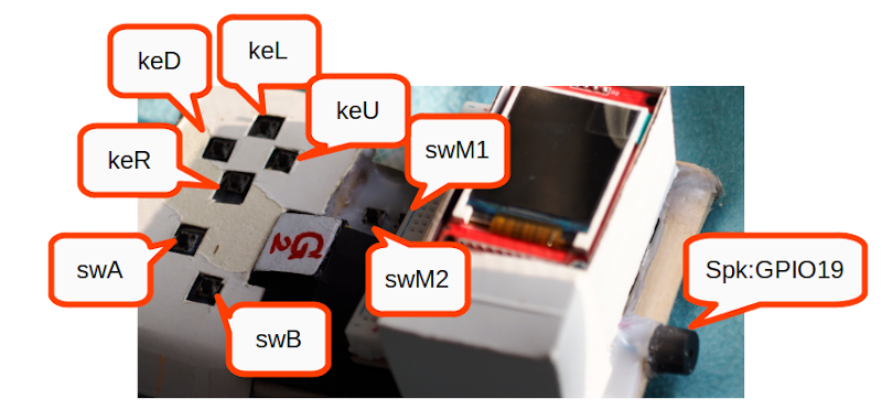
This article discusses the use of PWM (Pulse Width Modulate) of the ESP32 microcontroller in the Arduino framework after discussing the functionality of this section in the ESP-IDF and MicroPython by connecting the board to the speaker as shown in Figure 1.
Commands
The use of PWM in the Arduino framework of the esp32 microcontroller consists of 3 steps:
- Set to configure the frequency and resolution of duty values.
- Connect the settings to the signal output pin.
- Send duty values to the signal output pin.
From these three steps, the instructions for use and the details of the commands are given in the following sections.
Settings
The PWM configuration method must be set via ledcSetup() to enable the desired channel to generate a certain frequency and the resolution of the value range is as follows.
ledcSetup( ch, freq, resolution )
This setting affects the frequency delivered to devices using the specified channel. In this way, if we set the frequency to the same frequency as the music note will result in the sound of that note.
The resolution can be in the range of 1 bit to 16 bits, depending on the needs of the programmer that wants to control the resolution of the duty cycle configuration at any level. For example, if set to 8 bits, the duty value can be set to 0 to 255, and if set to 12 bits, the duty value range can be set from 0 to 4095, etc.
Pin assignment
The command to specify which pin acts as PWM must use the command ledcAttachPin() by specifying the PIN and the selected channel number as in the following format.
ledcAttachPin( pin, ch )
Sending data to the pin
To pass duty values to a given pin, you must use the ledcWrite() command. Specify the pin to be removed and the required duty value as follows.
ledcWrite( pin, duty )
From this command, it will be found that the duty setting makes the volume of the sound more or less.
Example Code
The following example program is playing notes C5, D5, F5, G5, A5, B5 and C6 when the player presses keL, keU, keD, keR, swM1, swM2, swA and swB through the speakers connected to pin GPIO19.
#include <Arduino.h>

#define spk 19
#define spkCh 0
#define keL 39
#define keU 34
#define keD 35
#define keR 32
#define swM1 33
#define swM2 25
#define swA 26
#define swB 27

uint8_t input[] = {
  keL, keU,  keD, keR, swM1, swM2, swA, swB
};

uint16_t freq[] = {
  523, 587, 659, 698, 784, 880, 988, 1047
};

void setup() {
  Serial.begin(115200);
  int i;
  for (i = 0; i < 8; i++) {
    pinMode(input[i], INPUT_PULLUP);
  }
  pinMode( spk, OUTPUT );
  ledcSetup( spkCh, 0, 8 );
  ledcAttachPin( spk, spkCh );
}

int8_t pressed = 0;
void loop() {
  for (int idx = 0; idx < 8; idx++) {
    if (digitalRead( input[idx] ) == 0) {
      if (pressed == idx + 1) {
        ledcWrite( spkCh, 100 );
        break;
      }
      ledcSetup( spkCh, freq[idx], 8 );
      ledcAttachPin( spk, spkCh );
      ledcWrite( spkCh, 100 );
      pressed = idx + 1;
      Serial.printf("%d [%d] pressed\n", input[idx], freq[idx]);
      break;
    }
  }
  delay(200);
  ledcWrite( spkCh, 0 );
}
Conclusion
From this article, we will see that by using PWM with the ESP32 microcontroller we can generate frequency and set the loudspeaker volume by setting the frequency from ledcSetup() and ledcWrite() which can be applied to playing music. In addition, by using PWM, programmers do not need to write their loops to send 0 or 1. Finally, have fun with programming.
(C) 2020-2022, By Jarut Busarathid and Danai Jedsadathitikul
Updated 2022-02-01