[EN] Generate temperature and humidity graphs with data from Singly Linked List.

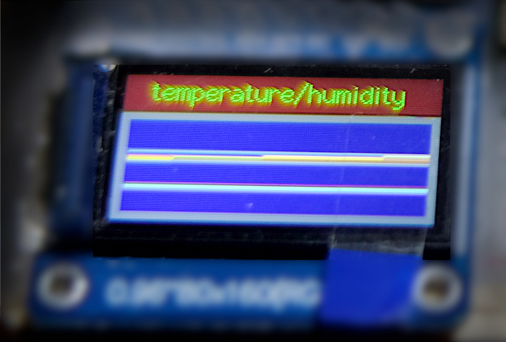
From the article Singly Linked List Data Structures, the use of the DHT11 sensor module with the STM32F103 microcontroller, and the use of the TFT display module based on the st7735s controller, the idea of this article is to take an example of using a singly linked list data structure to collect the temperature and humidity values to find the maximum, minimum, average, together with the data in the list to display in the form of a graph as shown in Figure 1.

Figure 1 Result of the article
Read More

[EN] Singly Linked List

This article is about programming C/C++ with Arduino Nano, Arduino Uno, LGT8F328P or other boards with C-capable platforms. A pointer is used to point to a memory address and memory management methods, including memory reservation memory access and deactivating the use of memory to create a method for storing data in a Single Linked List along with an example program used to store a list of temperature and humidity values ​​from the DHT11 module as shown in Figure 1.

Figure 1 Microcontroller with LGT8F328P and DHT11 module
Read More

[EN] Arduino: STM32F103CBT6 ADC&LDR.

From reading articles on how to use board STM32L432 ADC and articles about STM32F103x connecting to ST7735S, it’s time to take STM32F103CBT6 or Blue-Pill/Black-Pill board. Let’s write a program to use ADC to display on a TFT screen. The example of the result of this article is as shown in Figure 1, which is reading from Pin PA0 that has been connected to Pin Analog signal from Board LDR in Figure 2 to Displayed on a TFT display.

Figure 1 Our board’s operation
Read More

[EN] Arduino: ESP32-S2’s DAC&ADC.

After testing the DAC and ADC of both the ESP32, SAM-D21, LGT8F328P and STM32L432KC, This time, it’s the time of the ESP32-S2 that we have. The test performance is still the same as before using the DAC. Three types of waves are sent out: zigzag, triangular, and sine waves and connect to the ADC pin to read the value and test the graph to see what it looks like.

In this experiment, DAC1 is connected to the ADC as shown in Figure 1. The ESP32-S2 has 2 ports of 8-bit DAC called DAC1 and DAC2. The ADC has a 12-bit resolution, which is seen to have the same properties as the ESP32, but whether the results are the same or not, you can tell that they are probably different because they use different microcontrollers. The ESP32-S2 uses the same one as the ESP32-S3 with only one core and no BLE.

Figure 1 Neucleo L432KC with A3 connected to D3
Read More

[EN] Try the SoftHost USB library for ESP32.

This article is an example of using nathalis‘s ESP32 Soft Host to try and test it on an OLED display with a resolution of 128×64 dots as shown in Figure 1 to receive data from a keyboard or mouse, it uses only a few GPIO pins but receives data from a keyboard with a large number of keys. Normally, the ESP32 microcontroller does not support a direct USB connection, so it requires programming by using a timer to check the status of the pins D- and D+ to be assembled into data at the byte level and assembled into packs of data for further interpretation.

Figure 1 Connected devices and boards are illustrated in this article
Read More

[EN] Arduino: STM32L432 Nucleo-32’s DAC&ADC.

From reading the article Using STM32 Core Support for Arduino for Board Nucleo L432KC by Ajarn Rewat Siriphokapirom, we have provided the board to test and connect the pin for sending data output DAC to ADC as shown in Figure 1 to test the operation of the DAC and ADC of the board by using the working code like the ESP32 microcontroller board, SAM-D21 and LGT8F328P. Let’s get started.

Figure 1 Neucleo L432KC with A3 connected to D3
Read More

[EN] Arduino: The LGT8F328P’s ADC/DAC.

This article is a continuation of the previous article introducing the LGT8F328P board and its use of ADC and DAC. By focusing on the use for the chip LGT8F328P, which is different from the SAM-D21 in that it uses pin D4 as a pin that serves as DAC0 and the DAC circuit has a resolution of 8-bit.  The output can be from 0 to 255. The ADC sector uses pins A0, A1, … normally and has a resolution of 12 bits. Therefore, in this article, the connection pins from A0 to D4 are used in the experiment as shown in Figure 1.

Figure 1 LGT8F328P connected A0 to D4
Read More

[EN] Arduino ADC/DAC

This article introduces the ESP32 and SAM-D21 microcontroller board to learn how to use ADC (Analog to Digital Converter) and DAC (Digital to Analog Converter) instruction by connecting the DAC pin to ADC as shown in Figures 1 (Connect A0 to A1 of Board SAM-D21 ) and 2 (Connect Pin GPIO26 to GPIO36 of ESP32) to send data to DAC and have ADC read it back. Then send the results out to the serial port for display with the Serial Plotter, which is an example program to send 3 types of data, which is a zigzag graph, triangular graph and waveform graph from the sinusoidal function

Figure 1 SAM-D21 with A0 connected to A1
Figure 2 ESP32 with port 26 connected to port 36
Read More