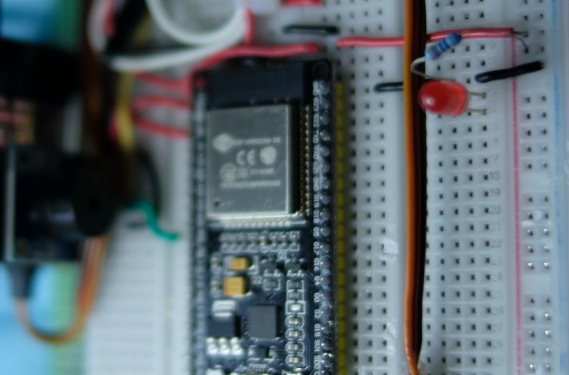
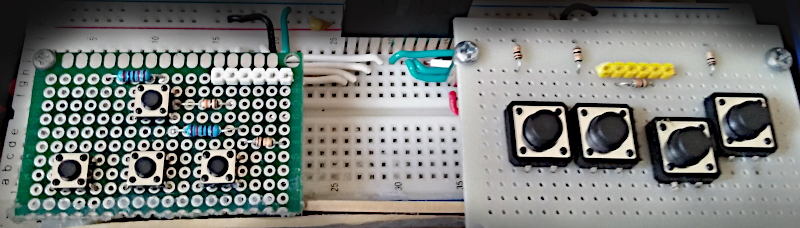
This article discusses the implementation of a servo motor module using the ESP32’s GPIO that outputs a digital PWM signal or Pulse Width Modulation or an LEDC (LED Control) which enables frequency band generation or adjust the proportion of status 1 and 0 in 1 waveform with a frequency of 50Hz using the experimental board as shown in Figure 1.
This article discusses the use of the ESP32’s GPIO to output digital signals such as PWM or Pulse Width Modulation or LEDC (LED Control), which enables frequency generation or adjusts the proportion of 1 and 0 states in 1 waveform. Thus, in the absence of the DAC, we can still adjust the average voltage at that pin as needed and it can be applied to control servo motors as well. Therefore, in this article, we will learn how to use PWM and apply it to frequency transmission instead of DAC (from the previous article) and LED dimming using the experimental board as shown in Figure 1.
This article discusses the use of the ESP32’s GPIO as an analog signal output through the 8-bit DAC module of the ESP32 microcontroller. In this article, we use Cosine wave generation to output the analog signal of the microcontroller through the speaker and show the waveform obtained from the oscilloscope display. The experimental board is still used as shown in Figure 1.
(Figure. 1 Connection and use of DAC examples)Read More
This article describes the use of the GPIO of ESP32 to output analog signal through 8-bit DAC module of ESP32 microcontroller by creating a zig graph (Figure 7) to the speaker module as shown in Figure 1.
This article discusses the use of the ESP32’s GPIO as an analog input. By using the voltage input circuit from adjusting values with an adjustable resistor as shown in Figure 1. So, in this article, we will learn how to use the ADC instruction of the ESP32 microcontroller and how to configure the value of ADC in menuconfig.
(Figure. 1 The implementation is illustrated with the example in this article)Read More
This article discusses the use of the ESP32’s GPIO to act as a digital signal import. By using the circuit of a keypad that is a switch of 8 that is made to look like a gamepad as in Figure 1.
This article discusses setting the GPIO and sending the digital status 0 or 1 to the port, starting with the LED on and off by connecting to the external LED circuit of the board as shown in Figure 1.
From the previous ulab article, it was found that Micropython can implement the same dataset processing instructions as used in Numpy through the previous ulab library v.0.54.0 which is the older version of ulab (currently v.3.0.1) brought up this article. This article describes how to create a Micropython that integrates the ulab library and uses it with SPIRAM versions of esp32.
(Figure. 1 Module list of ulab)
ulab3
From Figure 1, it can be seen that the structure of the ulab library has changed from the original. This causes the programming from the previous example to have to be modified. Under ulab there are libraries of numpy and scipy. The details of numpy that are supported are as follows.